3-11
Catalyst 3650 Switch Hardware Installation Guide
OL-29734-01
Chapter 3 Power Supply Installation
Installing a DC Power Supply
Installing the DC Power Supply in the Switch
Before installing the power supply, see the Installation Guidelines, page 3-5.
Step 1 Turn off DC power. To ensure that power is off, change the circuit breakers to the OFF position, and tape
the circuit-breaker switches in the OFF position.
Step 2 Remove the plastic safety cover from the power supply terminal blocks (Figure 3-4).
If you are not replacing a DC power supply, go to Step 5.
Step 3 Use a number-2 Phillips screwdriver to remove the DC-input power wires from the power terminals.
Step 4 Press the release latch at the right side of the power supply module inward, and pull the power supply out.
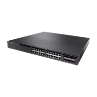
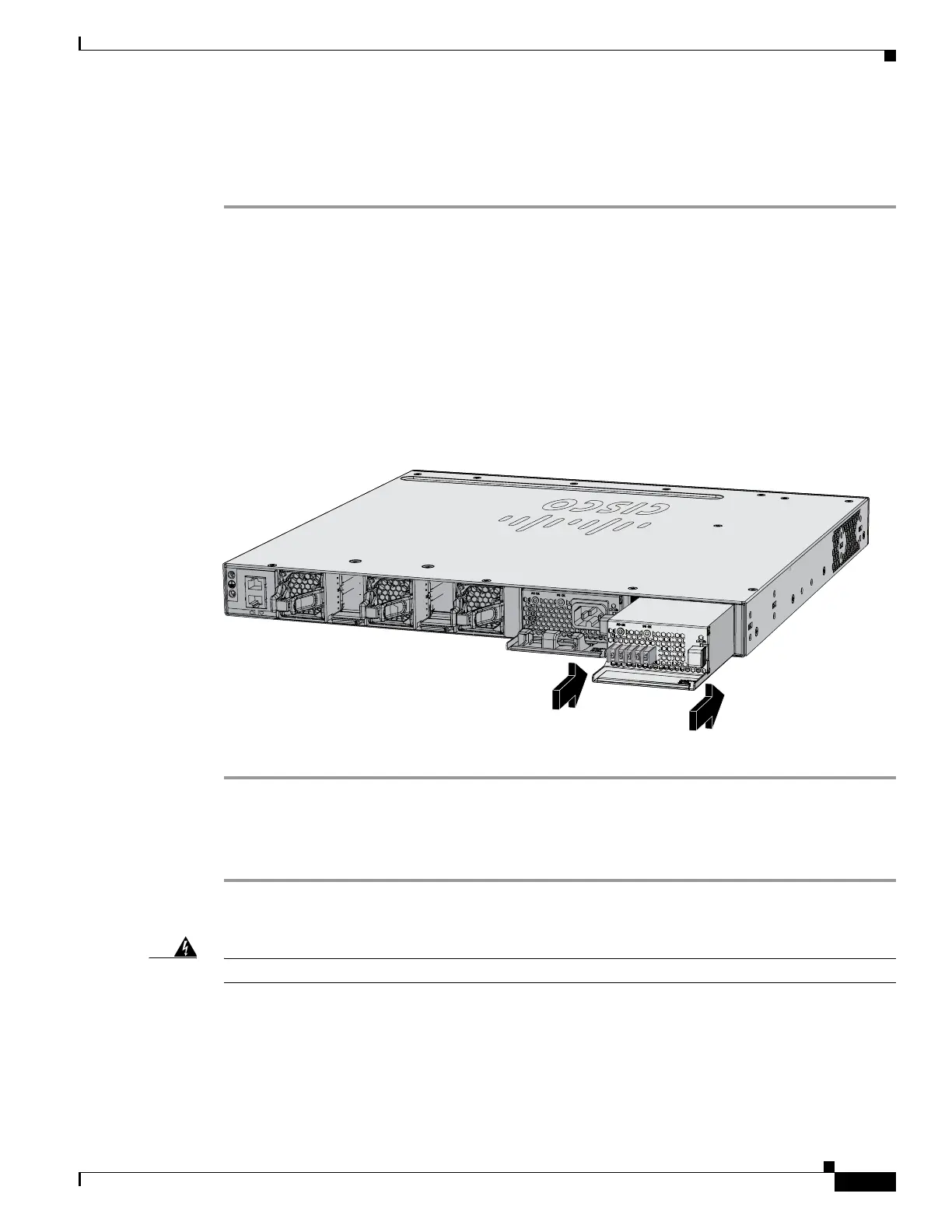
Step 5 Insert the power supply in the power-supply slot, and gently push it into the slot (Figure 3-11). When
correctly installed, the DC power supply (excluding the extraction handle) is flush with the switch rear
panel.
Figure 3-11 Inserting the DC Power Supply in the Switch
Step 6
Connect the input power as described in the “Wiring the DC Input Power Source” section.
Wiring the DC Input Power Source
Step 1 Using a wire-stripping tool, strip each of the four wires from the DC-input power source to the
appropriate length for the terminals.
Warning
Use copper conductors only.
Statement 1025
Step 2 Using a Panduit crimping tool, crimp the fork-type terminals to the copper conductor, 90C, 12-AWG DC
power input wires.
Step 3 Connect the DC-input power terminals to the terminal blocks. See Figure 3-12 or Figure 3-13. Make sure
to match the polarity (negative to negative, positive to positive) when connecting the wires to the
terminal blocks. Connect the ground wire to a grounded metal rack or to earth ground if the switch is not
in a grounded rack.
347792
PWR-C2-640WDC
PWR-C2-640WAC
CONSOLE
MGMT
 Loading...