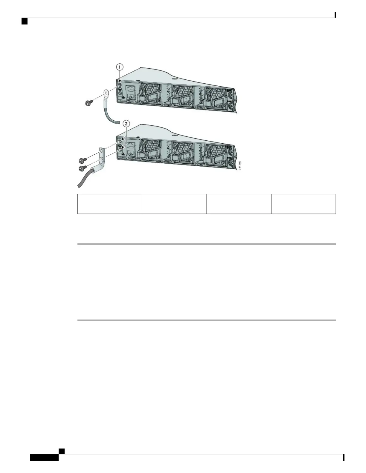
Figure 56: Attaching the Ground Lug and Wire Assembly
Dual-hole ground adapter
and dual-hole lug
2Single-hole ground screw
and lug ring
1
Step 6 Using a ratcheting torque screwdriver, torque the ground-lug screws to 60 lbf-in. (960 ozf-in.).
Step 7 Connect the other end of the grounding wire to an appropriate grounding point at your site or to the rack.
Installing the DC Power Supply in the Switch
Before you begin
Before installing the power supply, see the Installation Guidelines, on page 72.
Procedure
Step 1 Turn off DC power. To ensure that power is off, change the circuit breakers to the OFF position, and tape the
circuit-breaker switches in the OFF position.
Step 2 Remove the plastic safety cover from the power supply terminal blocks.
If you are not replacing a DC power supply, go to Step 5.
Note
Step 3 Use a number-2 Phillips screwdriver to remove the DC-input power wires from the power terminals.
Step 4 Press the release latch at the right side of the power supply module inward, and pull the power supply out.
Step 5 Insert the power supply in the power-supply slot, and gently push it into the slot. When correctly installed,
the DC power supply (excluding the extraction handle) is flush with the switch rear panel.
Catalyst 3850 Switch Hardware Installation Guide
OL-26779-0578
Power Supply Installation
Installing the DC Power Supply in the Switch
 Loading...