1-25
Catalyst 4500 E-Series Switches Installation Guide
OL-13972-01
Chapter 1 Product Overview
Power Supplies
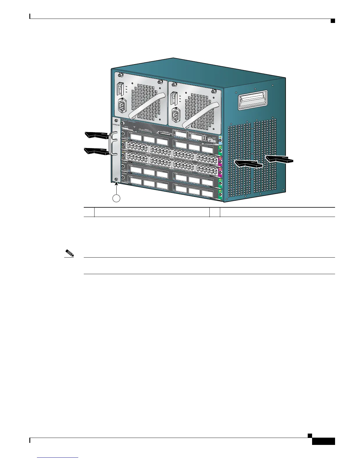
Figure 1-12 Catalyst 4506-E Airflow
Power Supplies
Note For detailed specifications on all Catalyst 4500 power supplies, refer to the “Catalyst 4507R-E Switch
Specifications” section on page A-3.
A Catalyst 4500 E-series switch can use a 1000 W, 1300 W, 1400 W, 2800 W (see Figure 1-13), or
4200 W (with two inputs, see Figure 1-14) AC-input power supply, a 1400 W DC-input power supply
with integrated PEM (see Figure 1-15), or a 1400 W DC multiple-input power supply (see Figure 1-16).
The power supplies are hot-swappable. If you have power supplies of different types installed in the two
bays, only one will be active and some power features will not be available. The power supply in the left
bay is PS1, the one in the right bay is PS2.
The AC-input power supply has a power cord that connects each power supply to the site power source.
The DC-input power supply is equipped with a input terminal block that is directly connected to the site
power wiring.
Each power supply has an ON/OFF switch that supplies power to the switch. For information on
removing and replacing power supplies, see the
“Removing and Replacing the Power Supply” section
on page 4-2.
1 Fan assembly
231365
4
5
0
6
1
 Loading...