3-5
Catalyst 4500 E-Series Switches Installation Guide
OL-13972-01
Chapter 3 Installing the Switch in a Rack
System Ground Connection Guidelines
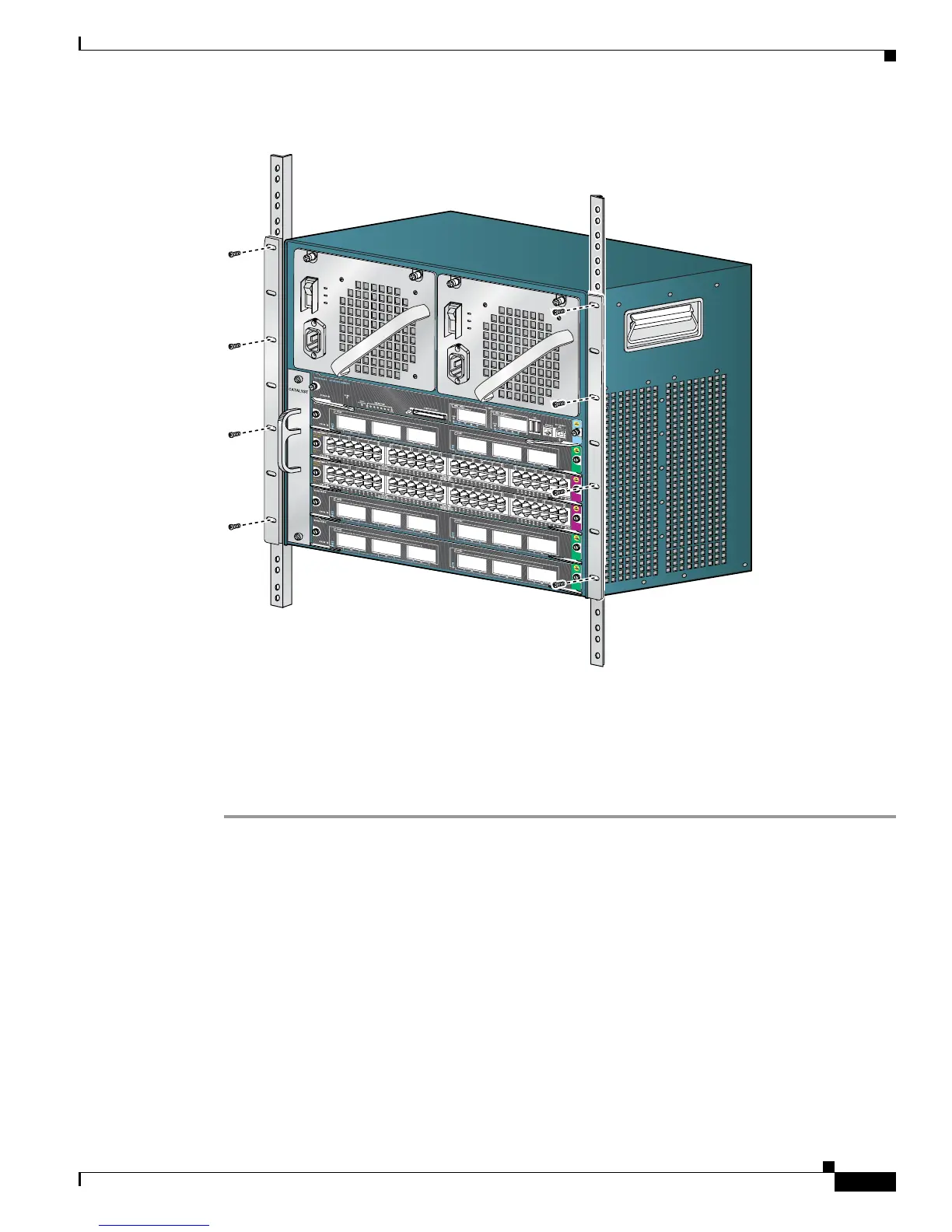
Figure 3-2 Installing a Catalyst 4506-E Switch in the Rack
Step 3 Make sure that the ejector levers are completely closed and the supervisor engine and switching modules
are installed securely.
Step 4 Tighten any loose captive installation screws on the supervisor engine and the switching module.
Step 5 Connect fiber and copper cables for switching traffic and uplinks or PoE as appropriate.
Step 6 Connect the switch to an appropriate ground. Refer to System Ground Connection Guidelines, page 3-5.
The system must have a ground connection before power is supplied to the switch.
System Ground Connection Guidelines
A grounding pad with two system (earth) grounding holes is provided in an enclosure near the left power
supply (PS1) on the Catalyst
4500 E-series switches (See Figure 3-3).
231371
4
5
0
6
 Loading...