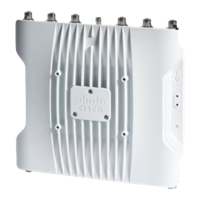
Powering the Access Point
The AP supports these power sources:
• DC power – 24–48 VDC
• Power-over-Ethernet (PoE)
The AP can be powered via the PoE input from an inline power injector or a suitably powered switch port.
Depending on the configuration and regulatory domain, the required power for full operation is 802.3at (PoE+)
or 24 - 48 VDC.
For more information, see Power Sources, on page 7 and Power Feature Matrix, on page 28.
Power Feature Matrix
The following table provides the AP power feature matrix.
Table 6: Cisco Catalyst IW9165D Heavy Duty Access Point Power Feature Matrix
RJ45 1GmGig EthGNSS5G/6G Radio5G RadioPower Input
Yesmax 2.5GYes2x22x224-48V
Yesmax 2.5GYes2x22x2802.3at
Nomax 1GYes1x11x1802.3af
Connecting a Power Injector
The AP supports the following power injector:
Table 7: Supporting Power Injectors
DescriptionPower Source
60W rated outdoor power injector, 5GEIW-PWRINJ-60RGDMG=
The power injector provides DC voltage to the AP over the Ethernet cable and supports a total end-to-end
Ethernet cable length of 100 m (328 ft) from the switch to the AP.
When an optional power injector powers your AP, follow these steps to complete the installation:
Step 1 Before applying PoE to the AP, ensure that the AP is grounded (see Grounding the Access Point, on page 26).
Step 2 Connect a CAT5e or better Ethernet cable from your wired LAN network to the power injector.
To reduce the risk of fire, use only No. 24 AWG or larger telecommunication line cord. Statement 1023
Warning
The installer is responsible for ensuring that powering the AP from this type of power injector is allowed by
local and/or national safety and telecommunications equipment standards.
Note
Cisco Catalyst IW9165D Heavy Duty Access Point Hardware Installation Guide
28
Installation Overview
Powering the Access Point
 Loading...