1-71
Cisco CRS-1 Carrier Routing System to Cisco CRS-3 Carrier Routing System Migration Guide
OL-13669-03
Chapter 1 Migrating to a Cisco CRS-3 Carrier Routing System
How to Migrate to a Cisco CRS-3 Carrier Routing System (4-Slot)
Note You may hear a crunching noise when seating the card; this noise is normal.
Step 13 Use the screwdriver to turn the two captive screws on the front panel of the CRS-3 fabric card clockwise
to seat the card firmly in the slot.
What to Do Next
After performing this task, you may replace any front cosmetic cover plates (see the “Installing the Front
and Rear (SFC) Side Cosmetic Components” section in the Cisco CRS Carrier Routing System 4-Slot
Line Card Chassis Installation Guide).
For complete information on regulatory compliance and safety, see Regulatory Compliance and Safety
Information for the Cisco CRS Carrier Routing System. For information on removing the front cosmetic
cover plates, see the “Removing the Rear (OIM) Side Cosmetic Components” section in the Cisco CRS
Carrier Routing System 4-Slot Line Card Chassis Installation Guide. For information on how to power
down your chassis, see the “Powering an AC Power Shelf Energized Chassis Up and Down” section in
the Cisco CRS Carrier Routing System 4-Slot Line Card Chassis Installation Guide or the “Powering a
DC Power Shelf Energized Chassis Up and Down” section in the Cisco CRS Carrier Routing System
4-Slot Line Card Chassis Installation Guide. For information on installing an OIM, see the “Installing
an OIM” section in the Cisco CRS Carrier Routing System 4-Slot Line Card Chassis Installation Guide.
Verifying the Installation of the CRS-3 Fabric Card
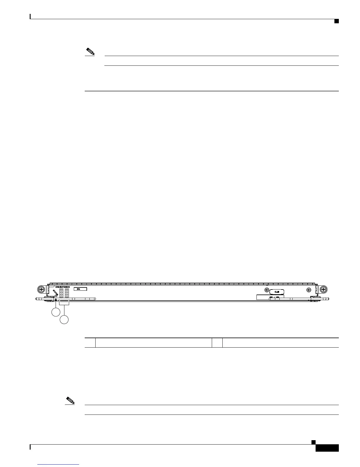
This section describes how to verify that a CRS-3 fabric card (QQ123-140G) has been properly installed.
Figure
1-15 is an illustration of the QQ123-140G switch fabric card front panel.
Figure 1-15 Switch Fabric Card Front View (QQ123-140G Shown)
Understanding the Alphanumeric LEDs
At one end of the faceplate, near an ejector lever, a CRS-3 fabric card has two four-digit alphanumeric
LED displays that show a sequence of messages indicating the state of the card. In normal operation, the
LED module should display
IOS-XR.
Note It is normal for some displayed messages to appear too briefly in the LED display to be read.
1 Status LED 2 Alphanumeric LEDs
 Loading...


