B-46
Cisco IE 3000 Switch Hardware Installation Guide
Appendix B Installation In a Hazardous Environment
Connecting Destination Ports
You can populate the switch or expansion module ports with a combination of rugged SFP transceiver
types. Not all SFP transceiver types are supported. See the Cisco IE 3000 release notes for the list of
supported SFP transceiver. SFP transceiver types must match on both ends of the network cable and the
length of thenetwork cable must not exceed the stipulated cable length for reliable communications.
Supported cable lengths for the SFP transceiver types are listed in Table C-1 on page C-6.
Caution When you use commercial SFP transceiver types such as CWDM and 1000BX-U/D in the IE-3000-4TC
or IE-3000-8TC S switch SFP ports, reduce the maximum operating temperature by 59°F (15°C). The
minimum operating temperature is 32°F (0°C). The IEM-3000-4SM or the IEM-3000-8SM expansion
module SFP ports do not operate at 1Gbps.
For detailed instructions on installing, removing, and cabling the SFP module, see the SFP transceiver
documentation on cisco.com.
Installing SFP Transceivers into Module Ports
Note This procedure is applicable to SFP ports on either the switches or on the expansion modules.
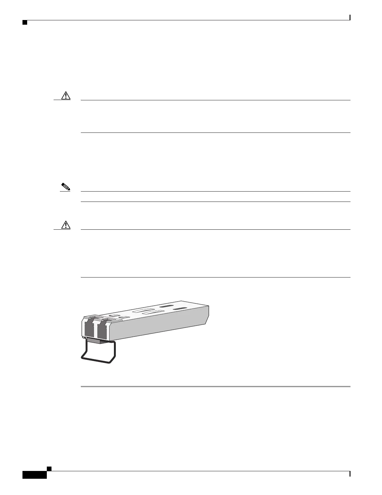
Figure B-32 shows an SFP transceiver that has a bale-clasp latch.
Caution We strongly recommend that you do not install or remove the SFP transceiver with fiber-optic cables
attached to it because of the potential damage to the cables, the cable connector, or the optical interfaces
in the SFP transceiver. Disconnect all cables before removing or installing an SFP transceiver.
Removing and installing an SFP transceiver can shorten its useful life. Do not remove and insert SFP
transceivers more often than is absolutely necessary.
Figure B-32 SFP Transceiver with a Bale-Clasp Latch
To insert an SFP module into the SFP module slot, follow these steps:
Step 1 Attach an ESD-preventive wrist strap to your wrist and to a grounded bare metal surface.
Step 2 Find the send (TX) and receive (RX) markings that identify the correct side of the SFP transceiver.
On some SFP transceivers, the send and receive (TX and RX) markings might be replaced by arrows that
show the direction of the connection, either send or receive (TX or RX).
Step 3 Align the SFP transceiver sideways in front of the SFP socket opening.
 Loading...