1-10
Cisco IE 3000 Switch Hardware Installation Guide
Chapter 1 Overview
Front-Panel Description
100BASE-FX Ports
The IEEE 802.3u 100BASE-FX ports provide full-duplex 100 Mb/s connectivity over multimode fiber
(MMF) cables. These ports use a small-form-factor fixed (SFF) fiber-optic transceiver module that
accepts a dual LC connector. The cable can be up to 1.24 miles (2 km) in length.
100BASE-X Ports
The IEEE 802.3u 100BASE-X ports provide full-duplex 100 Mb/s connectivity over both single-mode
(SMF) and multimode fiber (MMF) cables. These ports use a small-form-factor pluggable (SFP)
fiber-optic transceiver module that accepts a dual LC connector (except in the case of the
GLC-FE-100BX-U and GLC-FE-100BX-D SFP transceivers). With the GLC-FE-100ZX SFP
transceiver installed, cable runs of up to 49.6 miles (80 km) are supported.
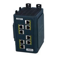
PoE Ports
The IEM-3000-4PC and the IEM-3000-4PC-4TC expansion modules provide 10/100BASE-T PoE
capability to the IE3000 base switch. Both expansion modules support up to 4 PoE (802.3af) or 4 PoE+
(802.3at) devices. The PoE expansion modules require a dedicated power supply for PoE power.
Power and Relay Connector
You connect the DC power and alarm signals to the switch through two front panel connectors. One
connector provides primary DC power (supply A) and the major alarm signal, and a second connector
(supply B) provides secondary power and the minor alarm signal. The two connectors are physically
identical and are in the upper left side of the front panel. See Figure 1-2.
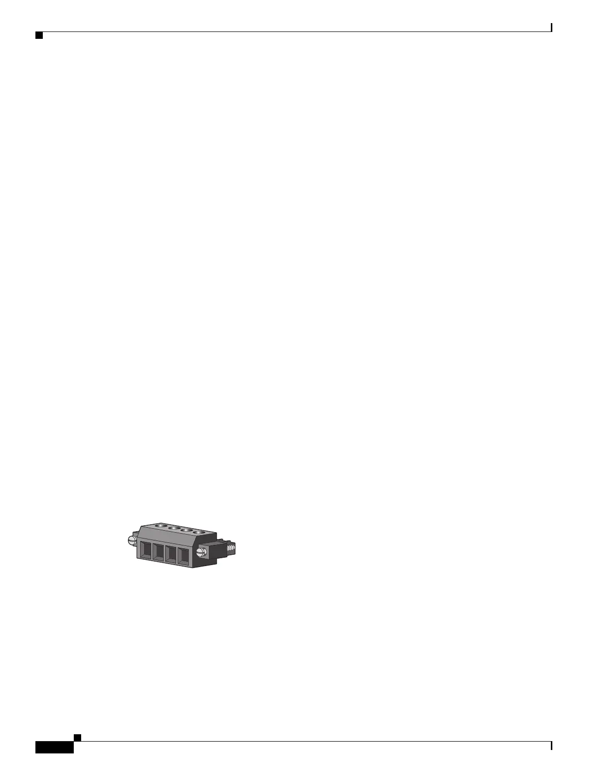
The switch accessory pack includes the mating power and relay connectors. These connectors provide
screw terminals for terminating the DC power and alarm wire and the connector plugs into the power
and relay receptacles on the front panel. The positive DC power connection is labeled V, and the return
connection is labeled RT (see Figure 1-9).
Figure 1-9 Power and Relay Connector
The switch can operate with a single power source or with dual power sources. When both power sources
are operational, the switch draws power from the DC source with the higher voltage. If one of the two
power sources fail, the other continues to power the switch.
The power and relay connectors also provide an interface for two independent alarm relays: the major
and the minor alarms. The relays can be activated for environmental, power supply, and port status alarm
conditions and can be configured to indicate an alarm with either open or closed contacts. The relay itself
is normally open, so under power failure conditions, the contacts are open. From the CLI, you can
associate any alarm condition with one or with both alarm relays.
 Loading...