C-10
Cisco IE 3000 Switch Hardware Installation Guide
Appendix C Cable and Connectors
Cable and Adapter Specifications
Crossover Cable and Adapter Pinouts
This section describes how to identify a crossover cable and also describes the adapter pinouts.
Identifying a Crossover Cable
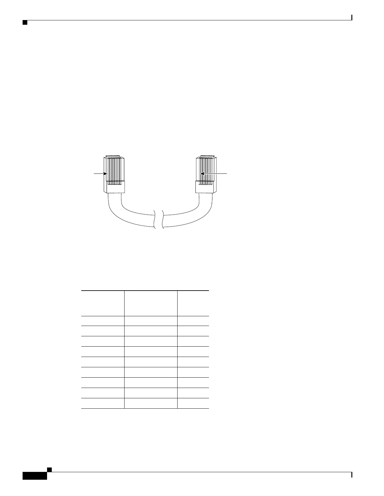
To identify a crossover cable, compare the two modular ends of the cable. Hold the cable ends
side-by-side, with the tab at the back. The wire connected to the pin on the outside of the left plug should
be a different color from the wire connected to the pin on the inside of the right plug. (See Figure C-9.)
Figure C-9 Identifying a Crossover Cable
Adapter Pinouts
Table C-2 lists the pinouts for the console port, the RJ-45-to-DB-9 adapter cable, and the console device.
Pin 1
200915
Pin 1
Pin 1 on one connector and
pin 1 on the other connector
should be different colors.
Table C-2 Console Port Signaling Using a DB-9 Adapter
Switch
Console
Port (DTE)
RJ-45-to-DB-9
Terminal Adapter
Console
Device
Signal DB-9 Pin Signal
RTS 8 CTS
DTR 6 DSR
TxD 2 RxD
GND 5 GND
GND 5 GND
RxD 3 TxD
DSR 4 DTR
CTS 7 RTS
 Loading...