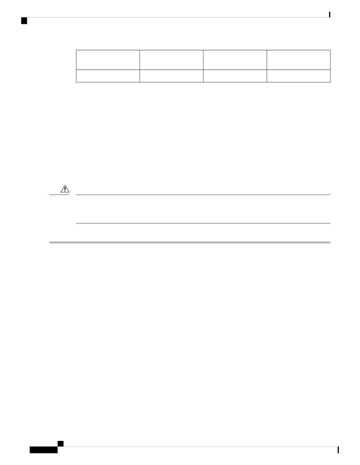
Electrical connection to
the module circuitry
340GBASE QSFP+
transceiver body
1
Bail-clasp latch2
Required Tools and Equipment
You need these tools to install the 40-Gigabit QSFP+ / 100-Gigabit QSFP28 transceiver modules:
• Wrist strap or other personal grounding device to prevent ESD occurrences.
• Antistatic mat or antistatic foam to set the transceiver on.
• Fiber-optic end-face cleaning tools and inspection equipment.
Installing the 40-Gigabit QSFP+ or 100-Gigabit Transceiver Module
The QSFP+ or QSFP28 transceiver module can have either a bail-clasp latch or a pull-tab latch. Installation
procedures for both types of latches are provided.
The QSFP+ or QSFP28 transceiver module is a static-sensitive device. Always use an ESD wrist strap or
similar individual grounding device when handling QSFP+ or QSFP28 transceiver modules or coming into
contact with system modules.
Caution
To install an QSFP+ or QSFP28 transceiver module, follow these steps:
Step 1 Attach an ESD wrist strap to yourself and a properly grounded point on the chassis or the rack.
Step 2 Remove the QSFP+ or QSFP28 transceiver module from its protective packaging.
Step 3 Check the label on the QSFP+ or QSFP28 transceiver module body to verify that you have the correct model for your
network.
Step 4 For optical QSFP+ or QSFP28 transceiver modules, remove the optical bore dust plug and set it aside.
Step 5 For QSFP+ or QSFP28 transceiver modules equipped with a pull-tab, hold the transceiver so that the identifier label is
on the top.
Step 6 For QSFP+ or QSFP28 transceiver modules equipped with a bail-clasp latch, keep the bail-clasp aligned in a vertical
position.
Step 7 Align the QSFP+ or QSFP28 transceiver module in front of the module’s transceiver socket opening and carefully slide
the QSFP+ or QSFP28 transceiver into the socket until the transceiver makes contact with the socket electrical connector
(see the figure below).
Hardware Installation Guide for Cisco NCS 5700 Series Fixed-Port Routers
78
Connect Router to the Network
Required Tools and Equipment
 Loading...