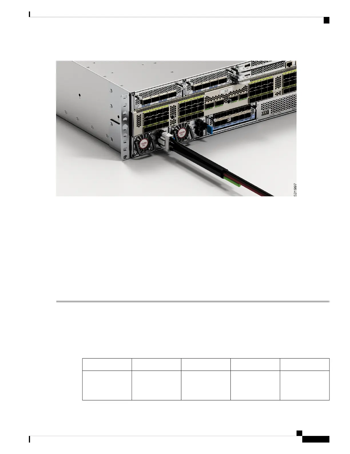
Figure 47: NCS-57C3-MOD - Connecting DC Power
Step 3 Dress the power according to local practice.
Step 4 Connect the office battery and return cables according to the fuse panel engineering specifications.
Step 5 Insert the DC connector into the DC receptacle on the power supply.
After the connection, the black color (DC negative) wire appears on top.
To connect the PSU2KW-DCPI power supply module with the power source, you must procure the
PWR-2KW-DC-CBL power cord.
Note
To connect the NC57-1600W-DCFW power supply module with the power source, you must procure the
CAB-48DC-40A-8AWG power cord.
Note
Step 6 Ensure that the locking mechanism has engaged to secure the cable.
Step 7 Turn on the circuit breaker at the power source.
Power Supply Unit Input and Output Ranges
This table summarises input and output power ranges for PSU low line and nominal applications:
Table 11: Input and output power ranges for PSUs
OutputOutput PowerInput Current (Max)Input VoltagePID
12V/84A1000W12A100-127V acPSU2KW-ACPI
For low line
applications
Hardware Installation Guide for Cisco NCS 5700 Series Fixed-Port Routers
59
Install the Chassis
Power Supply Unit Input and Output Ranges
 Loading...