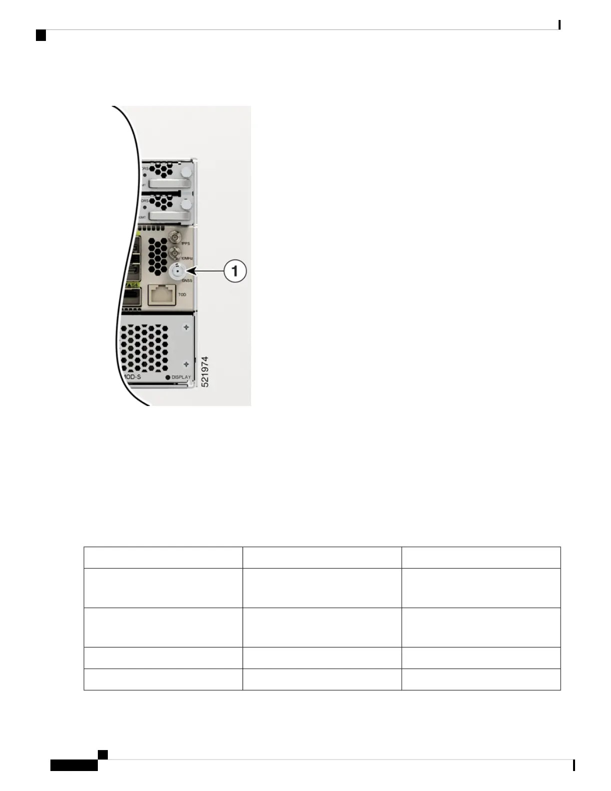
Figure 68: NCS-57C3-MOD GNSS Port
The GNSS RF In coaxial cable shield must be connected to the Facility Equipment Ground through the chassis. The
chassis must have the ground wire connected to the Facility Equipment Ground.
GPS Port Pinouts
The platform is capable of receiving or sourcing GPS signals of 1 PPS & 10 MHz. These interfaces are provided by two
mini-coax 50-Ohm, 1.0/2.3 DIN series connector on the front panel. Similarly there are two mini-coax 50-Ohm connectors
provided in the front panel to output this 1PPS and 10MHz.
The table below summarizes the GPS port pinouts.
Table 13: GPS Port Pinouts
1PPS (Input and Output)10 MHz (Input and Output)
Input—Rectangular pulse
Output—Rectangular pulse
Input—Sine wave
Output—Square wave
Waveform
Input— > 2.4 volts TTL compatible
Output— > 2.4 volts TTL compatible
Input— > 1.7 volt p-p(+8 to +10 dBm)
Output— > 2.4 volts TTL compatible
Amplitude
50 ohms50 ohmsImpedance
26 microseconds50% duty cyclePulse Width
Hardware Installation Guide for Cisco NCS 5700 Series Fixed-Port Routers
84
Connect Router to the Network
Connecting a Cable to the GNSS Antenna Interface
 Loading...