3-4
Cisco PIX Security Appliance Hardware Installation Guide
78-15170-03
Chapter 3 PIX 506/506E
Connecting a Power Supply Module to the PIX 506/506E
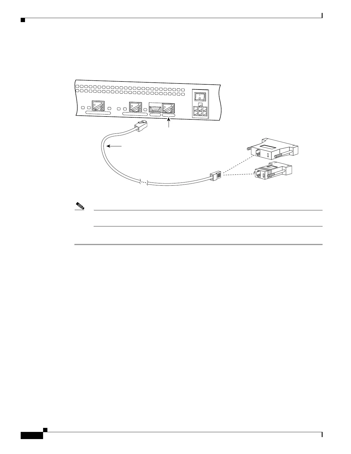
Step 2 Connect the RJ-45 connector to the PIX 506/506E and connect the other end to the serial port connector
on your computer (see Figure 3-7).
Figure 3-5 PIX 506/506E Serial Console Cable
Step 3 Connect the inside network cable to the interface connector marked ETHERNET 0 or ETHERNET 1.
Note The inside or outside network connections can be made to either interface port on the
PIX 506/506E.
Step 4 Connect the outside network cable to the remaining Ethernet port.
Connecting a Power Supply Module to the PIX 506/506E
This section describes how to connect the power supply module to the PIX 506/506E. Use this
information in conjunction with the Regulatory Compliance and Safety Information document.
The PIX 506/506E uses an external AC to DC power supply. Power is supplied to the PIX 506/506E by
connecting the power supply to the back of the security appliance and connecting a separate AC power
cord to the power supply.
C
O
N
S
O
L
E
E
T
H
E
R
N
E
T
0
ACT
LINK
LINK
DC
POWER
INPUT
ACT
U
S
B
E
T
H
E
R
N
E
T 1
38853
Console
port (RJ-45)
RJ-45 to
DB-9 or DB-25
serial cable
(null-modem)
Computer serial port
DB-9 or DB-25
 Loading...


