4-6
Cisco PIX Security Appliance Hardware Installation Guide
78-15170-03
Chapter 4 PIX 515/515E
Installing the PIX 515/515E
Installing the PIX 515/515E
To install the PIX 515/515E, perform the following steps:
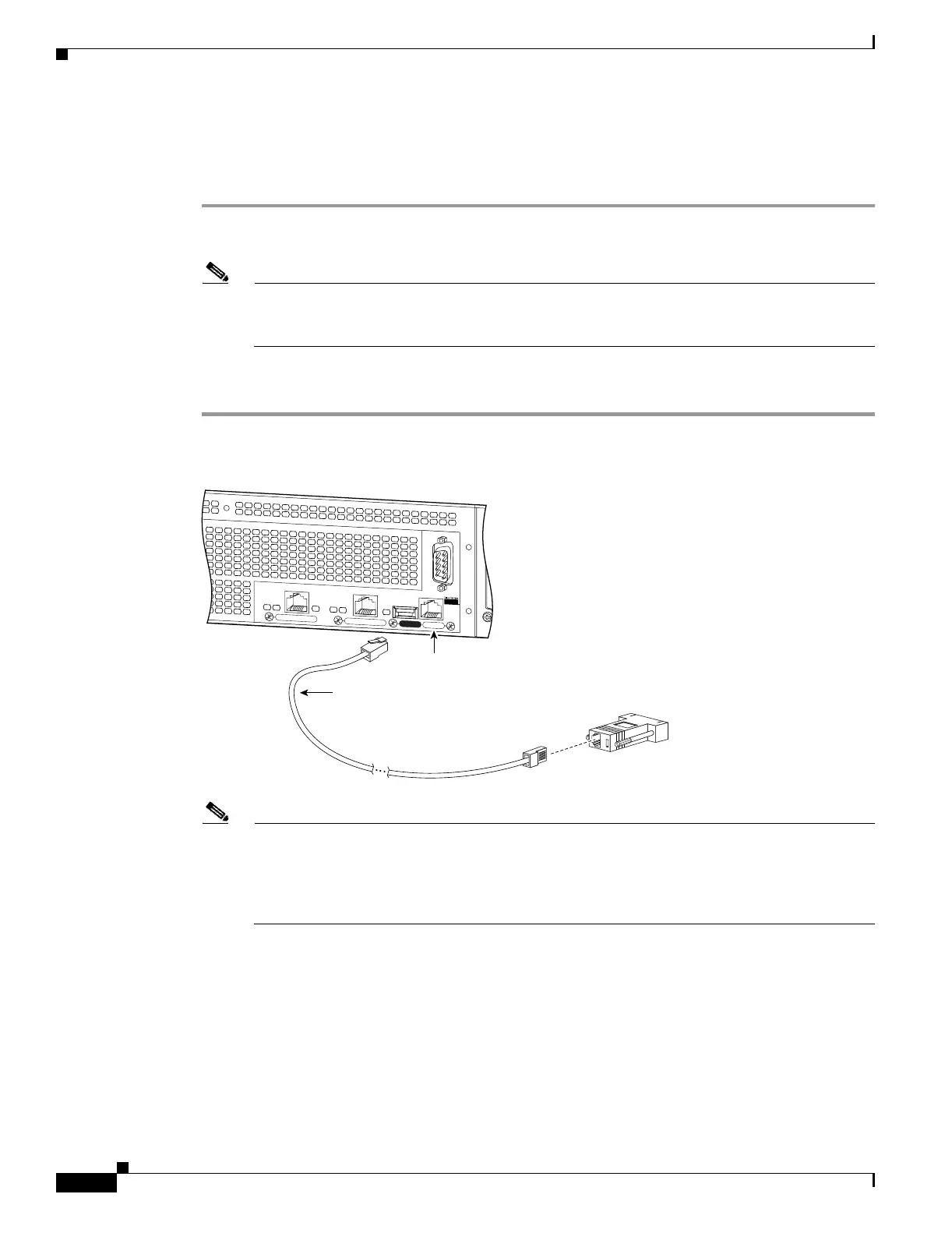
Step 1 Connect the cable as shown in Figure 4-7 so that you have either a DB-9 or DB-25 connector on one end
as required by the serial port for your computer, and the other end is the RJ-45 connector.
Note Use the Console port to connect to a computer to enter configuration commands. Locate the
serial cable from the accessory kit. The serial cable assembly consists of a null modem cable
with RJ-45 connectors, and one DB-9 connector and a DB-25 connector.
Step 2 Connect the RJ-45 connector to the PIX 515/515E Console port and connect the other end to the serial
port connector on your computer.
Figure 4-7 PIX 515/515E Serial Console Cable
Note If your unit has a four-port Ethernet circuit board already installed, refer to Figure 4-8. (The
four-port Ethernet circuit board requires the PIX-515/515E-UR license to be accessed.) If it has
one or two single-port Ethernet circuit boards, refer to Figure 4-9. If you need to install an
optional circuit board, refer to the “Removing and Replacing the PIX 515/515E Chassis Cover”
section on page 4-13 for more information.
F
A
I
L
O
V
E
R
1
0
0
M
b
p
s
A
C
T
1
0
0
M
b
p
s
A
C
T
L
IN
K
L
IN
K
P
I
X
-
5
2
5
1
0
/1
0
0
E
T
H
E
R
N
E
T
1
1
0
/1
0
0
E
T
H
E
R
N
E
T
0
U
S
B
C
O
N
S
O
L
E
104944
PC terminal adapter DB-9
Console
port (RJ-45)
RJ-45 to
DB-9 or DB-25
serial cable
(null-modem)
 Loading...


