A-1
Cisco PIX Security Appliance Hardware Installation Guide
78-15170-03
APPENDIX
A
Cable Pinouts
The appendix provides the following pinout information:
• 10BaseT and 100BaseTX Connectors, page A-1
• Console Port (RJ-45), page A-2
• RJ-45 to DB-9 or DB-25 Serial Cable, page A-4
• Failover Cable Pinouts, page A-4
10BaseT and 100BaseTX Connectors
The 10BaseT and 100BaseTX ports use standard RJ-45 connectors. The 10BaseT and 100BaseTX ports
have their transmit (TD) and receive (RD) pairs internally crossed.
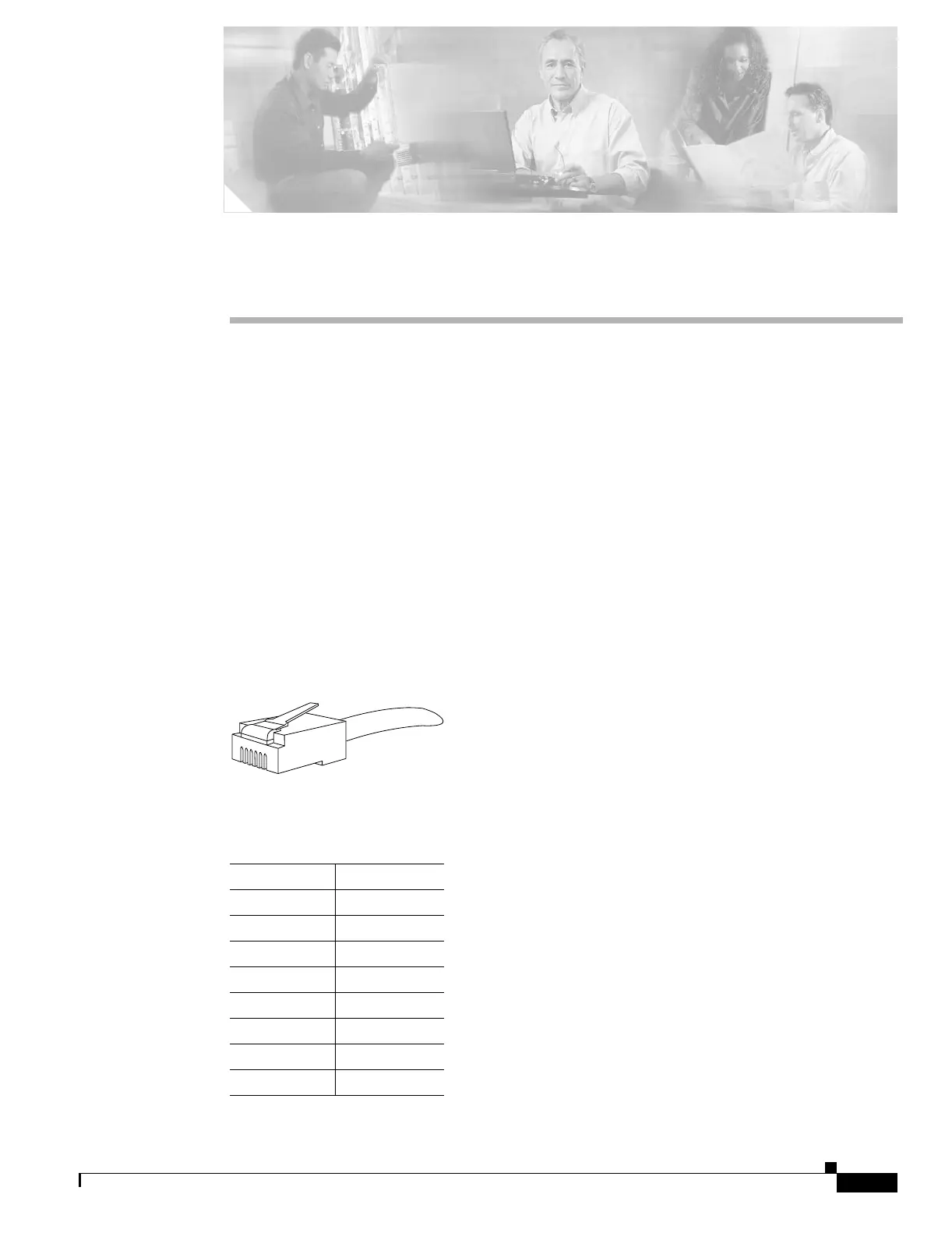
Figure A-1 shows the 10BaseT and the 100BaseTX connector (RJ-45).
Figure A-1 RJ-45 10BaseT and 100BaseTX Connector
Table A-1 shows the connector pinout.
H7316
Table A-1 10BaseT and 100BaseTX Connector (RJ-45) Pinouts
Pin Description
1TX+
2TX-
3RX+
4-
5-
6RX-
7-
8-
 Loading...


