A-4
Cisco PIX Security Appliance Hardware Installation Guide
78-15170-03
Appendix A Cable Pinouts
RJ-45 to DB-9 or DB-25 Serial Cable
RJ-45 to DB-9 or DB-25 Serial Cable
Table A-5 lists the cable pinouts for RJ-45 to DB-9 or DB-25.
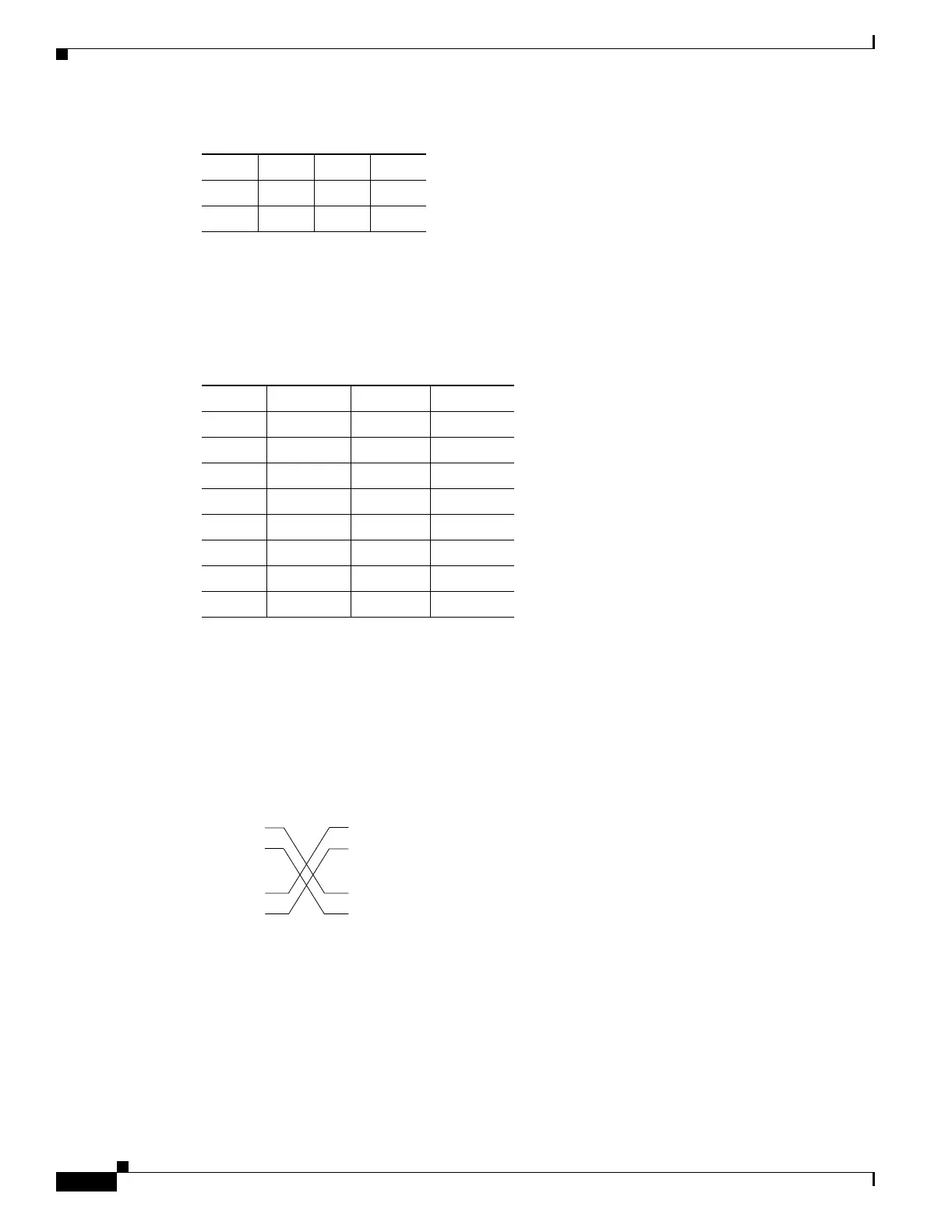
Failover Cable Pinouts
Figure A-4 shows the pinouts of a crossover cable, should you use this with the Stateful Failover
dedicated interface.
Figure A-4 Stateful Failover Dedicated Interface Crossover Cable Pinouts
- 72-
- 81-
Table A-4 RJ-45 Rolled (Console) Cable Pinouts (continued)
Signal Pin Pin Pin
Table A-5 Cable Pinouts for RJ-45 to DB-9 or DB-25
Signal RJ-45 Pin DB-9 Pin DB-25 Pin
RTS 8 8 5
DTR 7 6 6
TxD 6 2 3
GND 5 5 7
GND 4 5 7
RxD 3 3 2
DSR 2 4 20
CTS 1 7 4
Primary unit
3 TxD+
6 TxD–
1 RxD+
2 RxD–
3 TxD+
6 TxD–
1 RxD+
2 RxD–
28048
Secondary unit
 Loading...


