5-21
Cisco PIX Security Appliance Hardware Installation Guide
78-15170-03
Chapter 5 PIX 520
Installing the PIX 520 DC Model
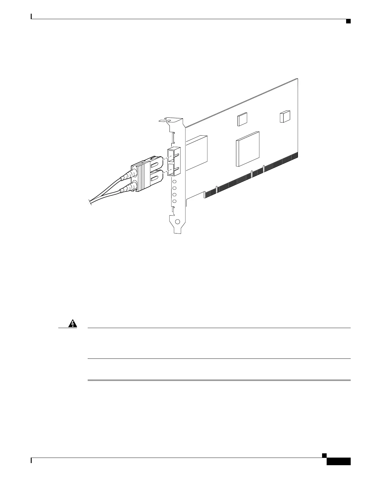
The Gigabit Ethernet circuit board and the fiber optic cable connection are shown in Figure 5-23.
Figure 5-23 Gigabit Ethernet Circuit Board
The Gigabit Ethernet circuit board has three LEDs:
• TX—Transmitting data
• RX—Receiving data
• LINK—The Gigabit Ethernet circuit board has established a network connection
Installing the PIX 520 DC Model
Warning
Before performing any of the following procedures, ensure that power is removed from the DC circuit.
To ensure that all power is OFF, locate the circuit breaker on the panel board that services the DC
circuit, switch the circuit breaker to the OFF position, and tape the switch handle of the circuit
breaker in the OFF position.
To install the PIX 520 DC power model, perform the following steps:
Step 1 Read the Regulatory Compliance and Safety Information document.
Step 2 Terminate the DC input wiring on a DC source capable of supplying at least 15 amps. A 15-amp circuit
breaker is required at the 48 VDC facility power source. An easily accessible disconnect device should
be incorporated into the facility wiring.
Step 3 Be sure the PIX 520 power is off by checking the power switch at the rear of the unit.
33010
T
X
R
X
LIN
K
 Loading...


