1-5
Cisco Video Surveillance PTZ IP Camera Installation Guide
OL-28954-01
Chapter 1 Overview
PTZ IP Camera Physical Details
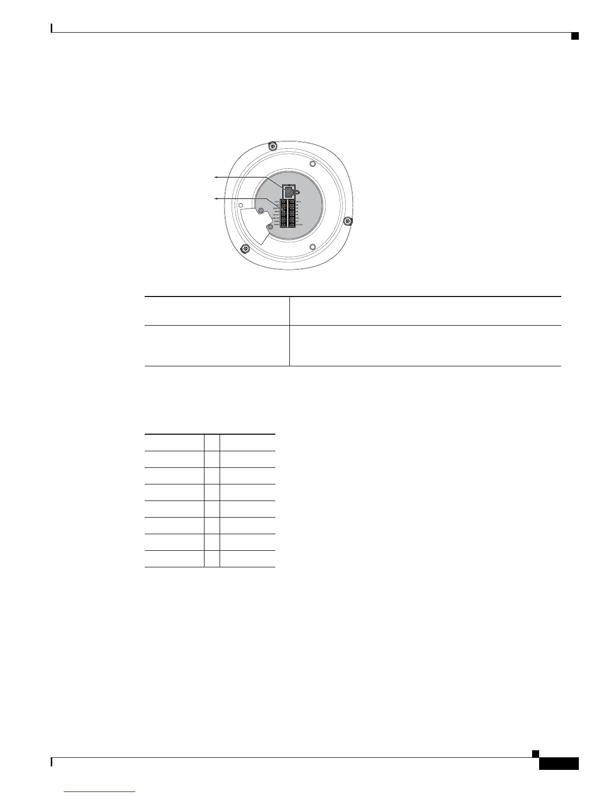
Figure 1-3 shows the interface view of the PTZ IP camera.
Figure 1-3 Interface View
Table 1-2 shows the order of the GPIO terminal block.
Ethernet 10/100 RJ45 Plug Plug for a standard LAN cable to connect the PTZ IP camera to
a 10/100BaseT router or switch.
General I/O Terminal Block General purpose input/output (GPIO) terminal block that is
used to connect external input and output devices. For more
information, see
Table 1-2.
347713
Ethernet 10/100
RJ45 Plug
General I/O
Terminal Block
Ta b l e 1-2 GPIO Terminal Block
AC24V DI GND
AC24V DI4
Reserved DI3
MIC IN DI2
Line OUT DI1
Audio GND DO2
RS485- DO1
RS485+ DO+(12V)
 Loading...