2-4
Cisco Video Surveillance PTZ IP Camera Installation Guide
OL-28954-01
Chapter 2 Installing the Camera
Installing the PTZ IP Camera
Cabling Through Waterproof Connectors
Perform the following steps to install and connect an external power cable and I/O cables for external
devices:
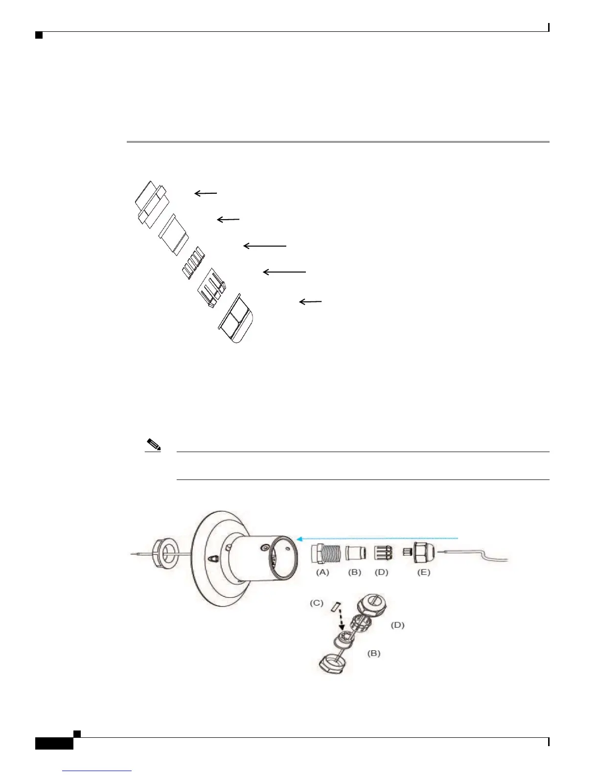
Step 1 Disassemble the components of the waterproof connector into parts (A)–(E).
Step 2 Remove the plastic stopper from the bottom of the dome cap and keep the M20 hex nut.
Step 3 Depending on the number of wires, remove seals (C) from the rubber seal (B).
Step 4 Feed the power cable through the waterproof connector (E --> D --> B --> A). Be sure to feed enough
power cable length through the waterproof connector to connect the power cable to the GPIO block.
The recommended cable gauge is 1.2–1.8 mm.
Note There are 16 holes on the seal (B), and the widest holes with a crack on the side are specific
for power cables.
Screw Nut (A)
Seal (B)
Seals (C)
Housing (D)
Sealing Nut (E)
 Loading...