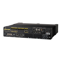
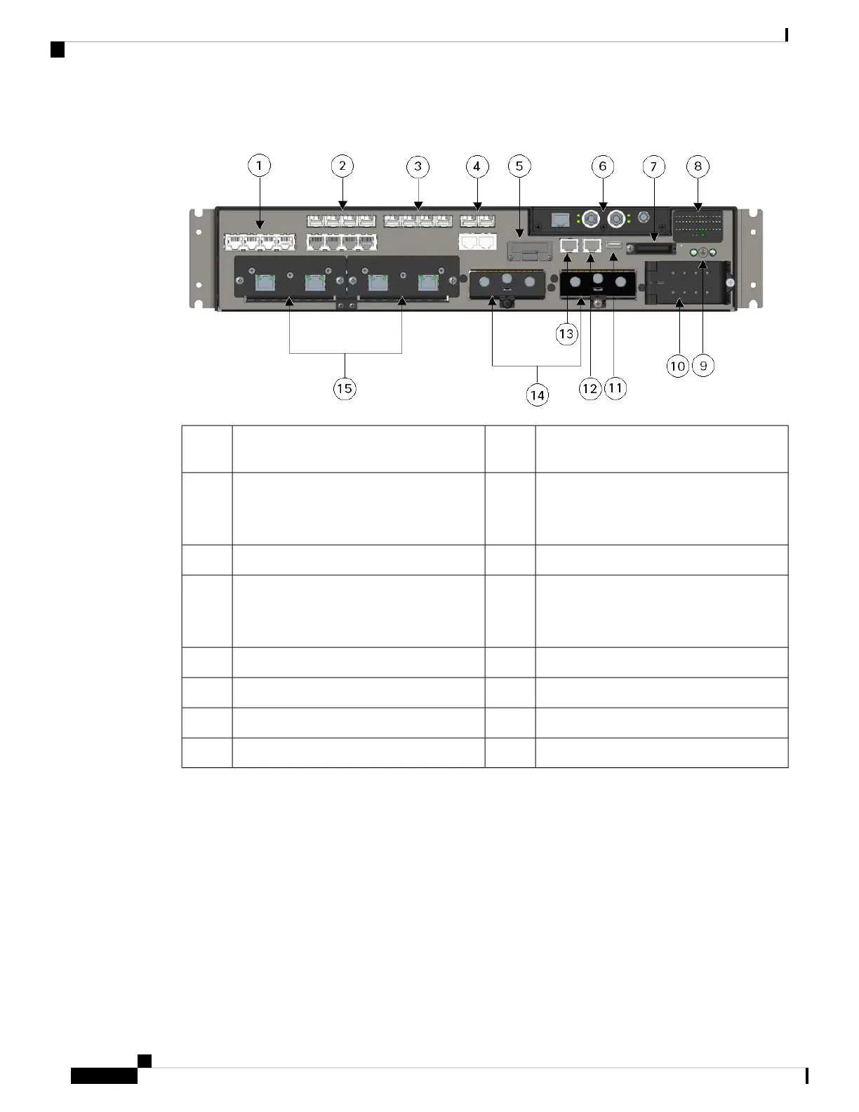
Figure 2: IR8340 Router Front Panel
Grounding point9Four 10/100/1000Base-T PoE/PoE+/UPoE
LAN ports
1
Power input terminal10Four 100/1000 SFP LAN ports (top)
Four 10/100/1000 Base-T LAN ports
(bottom)
2
USB port11Four 100/1000 SFP LAN ports3
Console port12Two 100/1000 SFP WAN ports (top)
Two 10/100/1000 Base-T WAN ports
(bottom)
4
Alarm port13mSATA module slot5
Two PIM slots14Timing module slot6
Two IRM-NIM slots15SD flash card slot7
System and port LEDs8
Alarm Ports
The router has two alarm inputs and one alarm output.
Alarm Input
The alarm input is a dry-contact alarm port. You can connect up to two alarm inputs from devices, such as a
door, a temperature gauge, or a fire alarm, to the alarm port. You can use the CLI to set the alarm severity to
minor, or major. An alarm generates a system message and turns on an LED. See Cable Side View LEDs, on
page 11 for the LED descriptions.
Cisco Catalyst IR8340 Rugged Series Router Hardware Installation Guide
2
Product Overview
Alarm Ports
 Loading...