Design & Selection
CAUTION
T h e ac t u a t o r s and d r i v e r s ar e not w a t e r p r o o f .
Provide waterproofing for use in places where water
or oil could come in contact with these devices.
Current leakage and faults could occur if swarf or
dust get onto the actuator or driver. Check that these
do not come in contact with devices.
Turning the main power on and off frequently may
cause damage to the element in the driver.
The output axis may move from the holding position
even
without an external force if the power or servo is
turned off.
Opt iona l mag net ic br akes are u sed t o enh anc e
holding rigidity during output shaft stoppage.
Do not use these brakes to brake or stop a rotating
output shaft.
The actuator and driver do not have a rust proof
guarantee.
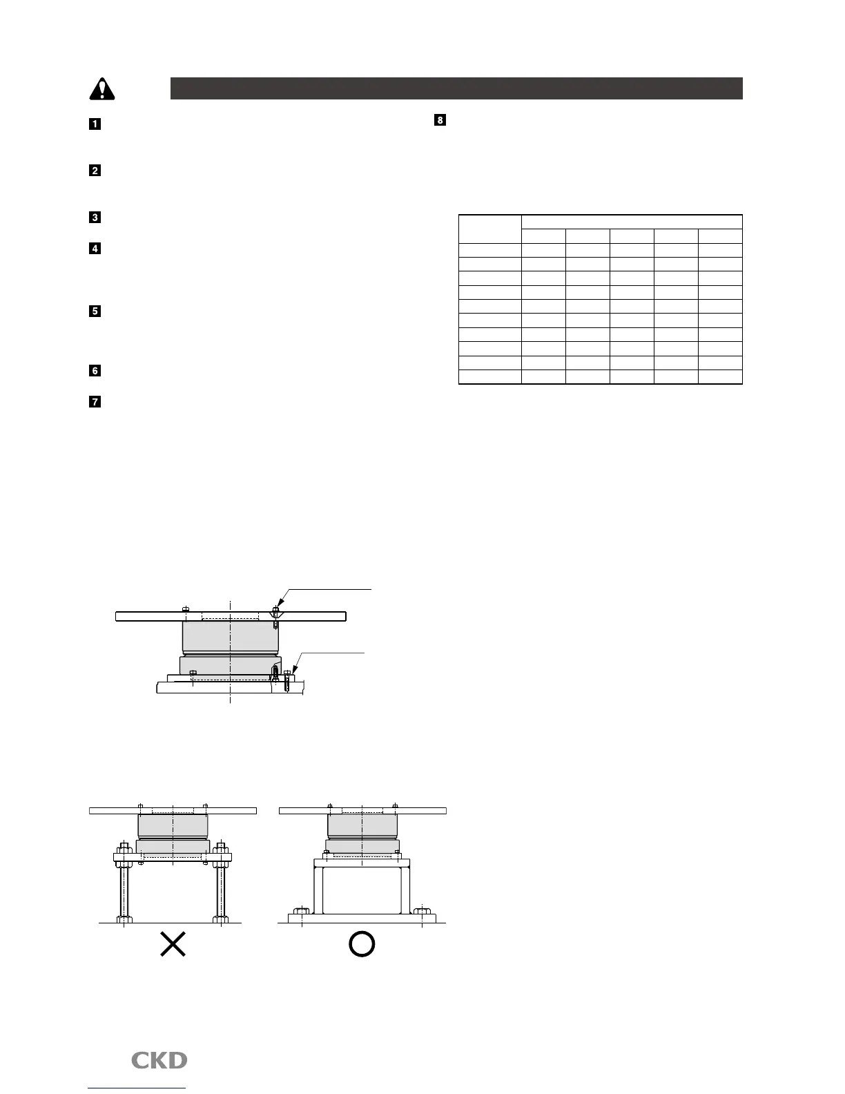
Equipment in w h ich d i r e ct d r i v e a c t u a tors a r e
installed should have sufficient rigidity to realize
full direct drive actuator performance. If the load
equipment or frame's mechanical unique vibration
is relatively low (200 to 300Hz or less), resonance
could occur in the direct drive actuator and load
equipment or frame. Secure the rotary table and main
unit installation bolts, and ensure sufficient rigidity
without loosening, etc. [Fig. 1]
Installing the actuator [Fig.1]
Gain must be adjusted based on load table size, etc.
[Fig.2] Even when the direct drive actuator is not
directly installed, it should be installed on a highly
rigid frame. [Fig.2]
[Fig.2] Mounting the actuator
When extending the outuput shaft, refer to table 1 as
a reference for deciding the extended shaft diameter
and length. Also, install a dummy inertia using fig. 3
as a reference.
[Table1] Reference of diameter for extended output shaft
Max. torque
[N
・
m]
Shaft extension(mm)
50 100 200 300 500
6 φ35 φ40 φ46 φ50 φ60
9,12 φ40 φ46 φ55 φ60 φ70
18,22 φ45 φ55 φ65 φ70 φ80
45 φ55 φ65 φ75 φ85 φ95
75 φ62 φ75 φ90 φ95 φ110
150 φ75 φ90 φ110 φ115 φ130
210 φ80 φ95 φ115 φ125 φ140
300
φ90 φ105 φ125 φ140 φ155
500 φ100 φ120 φ145 φ160 φ180
1000 φ120 φ140 φ170 φ185 φ210

 Loading...