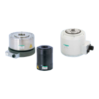
Intro14
Safety precautions
Always read this section before starting use.
Labor saving mechanisms warning
Installation & Adjustment
CAUTION
Connect the enclosed cable between the actuator
and driver. Check that excessive force is not applied
and the cable is not damaged. Do not modify the
en clo sed cab le (change the len gth or material)
because this could cause malfunction or faults.
Connect the correct power supply. Connecting a
undesignated power supply could cause faults. Wait
at least 5 seconds after turning power off before
turning it on again.
Securely fix the direct drive actuator to the machine,
and securely install loads such as the table before
adjusting gain. Confirm that no interference occurs
and t h a t safety i s s e c u r e d even w h e n f l e x i b l e
sections are rotated.
Do not tap the output shaft with a hammer, nor
assemble it forcibly. Failure to observe this would
prevent the expected accuracy or functions, and
could cause faults.
Do not place strong magnetic fields such as rare
earth magnets near the actuator. Failure to observe
th i s may ca u s e fa i l ur e s to mai n t ai n e xp e c t e d
accuracy.
T h e a c t u a t o r ma y be c o m e ho t de p e n d i n g o n
operating conditions. Provide a cover, etc., so that it
will not be touched by accident.
T h e ac t u a t o r m a y be c o m e h o t d e p e n d i n g o n
operating conditions.
Do not drill holes into the actuator. Contact CKD
when machining is required.
Do not get on the actuator or flexible parts such the
rotary table on the actuator during maintenance, etc.
Compatible type
If the actuator and driver are combined mistakenly
after program input (parameter setting), alarm
3 w i ll g o o f f . C h e c k t h e a c t u ator a nd d r iver
combination.
Note: Alarm 3 is to prevent malfunction if the
actuator and driver combination differ from
when the program was input. Alarm 3 is reset
when the program and parameters are input
again.
If operation is started with an incorrect actuator
and driver combinat i o n af t e r t h e pr o g r am i s
input (after parameter setting), it may result in
malfunctions and damages.
When changing the cable length or type, order the
cable separately.
Actuator may catch fire if an incompatible driver is
connected.
When using a circuit breaker, select one that has
higher harmonic measures for inverter use.
The position of the output shaft in the actuator
dimension drawing does not indicate the actuator's
origin. When using it at the output shaft shown in
dimension drawings, the origin must be adjusted to
the origin offset.
The body outlet cable on AX4009T and AX200T series
can not be moved. Always fix it at the connector
section so that it will not move. Also, refrain from
applying excess force onto the cable or pulling on
the cable since it may damage it.
Refer to the technical documents of the Abxodex
AX Series TS, TH type for other precautions and
conformity to standards
.
During Use & Maintenance
CAUTION
Do not disassemble the actuator, because this may
compromise expected functions and accuracy. Any
modification to the resolver could cause critical
damage.
When testing withstand voltage of the machine or
equipment containing th e direct driv e actuator,
disconnect the power cable for the driver and check
that the voltage is not applied to the driver. Failure to
observe this could result in faults.
If alarm "4" (actuator overload: electronic thermal)
goes off, wait for the actuator temperature to drop
before restarting.
Alarm "4" could occur in the cases below. Remove
the cause before resuming use.
R e s o n a n c e o r v i b r a t i o n : E n s u r e s u f f i c i e n t
installation rigidity.
Ta c t o r spe e d: I n c r e a s e m o v e m e n t t i m e or
stopping time.
Structure that locks the output shaft: Add M68,
M69 commands.
Actuator coordinates are recognized after power is
turned on so check that the output shaft does not
move for several seconds after power is turned on.
Refer to the technical documents of the Abxodex
AX Series TS, TH type for other precautions and
conformity to standards
.

 Loading...