INSTALLATION POWER UP SETUP USAGE GUIDE ADVANCED MENUS
INSTALLATIONPOWER UPSETUPUSAGE GUIDEADVANCED MENUS
6
31
In s t a l l a t I o n ad v a n c e d In s t a l l e r co n f I g u r a t I o n Me n u
Co n t r o l in S t a l l a t i o n lo C a t i o n
Locate the control on a vibration-free inside wall in an area having good air circulation.
The control should be located approximately ve feet high. The control should be
located in an area such that it is not inuenced by the following:
Drafts
Dead spots behind doors, in corners, or under cabinets
Cold or hot air from registers
Sunlight
Light from xtures or other appliance
Radiant heat from a replace or other heat source
Concealed water pipes (hot or cold)
Unconditioned areas behind the control
NOTE: It is recommended that multiple wires into a single terminal be twisted together prior to inserting into the plug
connector. Failure to do so may result in intermittent operation.
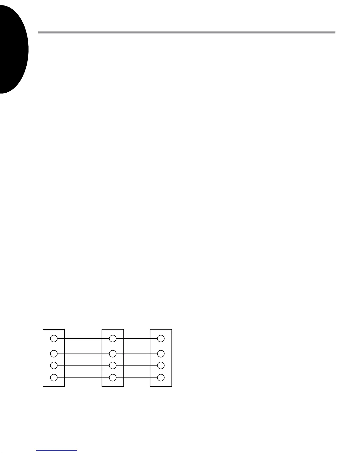
Wi r i n g re Q u i r e m e n t S
Each digitally communicating device in the system requires four wire connections:
24VAC Hot (R), 24VAC Common (C), Data 1 (1), and Data 2 (2). The R and C connections
provide a 24VAC power supply that can be shared between the indoor and outdoor units
and the thermostat. The data 1 and data 2 connections provide the communications bus
between the indoor unit, outdoor unit and thermostat. Thus, the R, C, 1, and 2 terminals
must be wired consistently. See the indoor unit and outdoor unit respective installation
manuals for additional wiring details.
Se n S o r S
Sub-menu Item Indication/User
Modiable Options
Comments
Outdoor Air
Temperature
(AIR TMP)
Displays the outdoor
air temperature
Sensor may or may not be available
on an air conditioner. Check air
conditioner instructions for details.
Outdoor Coil Tem-
perature (COIL TMP)
Displays the outdoor
coil temperature
Required for heat pump operation.
Co o l Se t -u P
Sub-menu Item User Modiable
Options
Comments
(applies to AC and HP models)
Cool Airow Trim
(CL TRM)
-10% to +10% in 2%
Increments
Selects the airow trim amount;
applies to air conditioner only.
Cool Airow Prole
(CL PRFL)
A, B, C, or D Selects the airow prole; applies to
air conditioner only.
Cool ON Delay
(CL ON)
5, 10, 20, or 30
seconds
Selects the indoor blower on delay;
applies to air conditioner only.
Cool OFF Delay
(CL OFF)
30, 60, 90, or 120
seconds
Selects the indoor blower o delay;
applies to air conditioner only.
Dehumidication
Select (DEHUM)
ON or OFF (default
is OFF)
Selecting “OFF” disables dehumidication;
selecting “ON” enables dehumidication;
applies to air conditioner only.
Indoor unit to thermostat wiring:
Connect a wire between terminal “R” on
the thermostat sub base and terminal
“R” on the 4-position plug connector for
the indoor unit. Repeat for the C, 1, and 2
terminals.
Indoor unit to outdoor unit wiring:
Connect a wire between terminal “R”
on the indoor unit’s 4-position plug and
the terminal “R” on the outdoor unit’s
4-position plug connector. Repeat for
the C, 1, and 2 terminals.
T o uchscreen
Thermostat
Indoor
Board T e rminal
Connections
Outdoor
Board T e rminal
Connections
R
C
1
2
R
C
1
2
R
C
1
2
24VAC (Hot)
24VAC
(Common)
Data 1
Data 2
 Loading...