INSTALLATION POWER UP SETUP USAGE GUIDE ADVANCED MENUS
INSTALLATIONPOWER UPSETUPUSAGE GUIDEADVANCED MENUS
30
7
In s t a l l a t I o nad v a n c e d In s t a l l e r co n f I g u r a t I o n Me n u
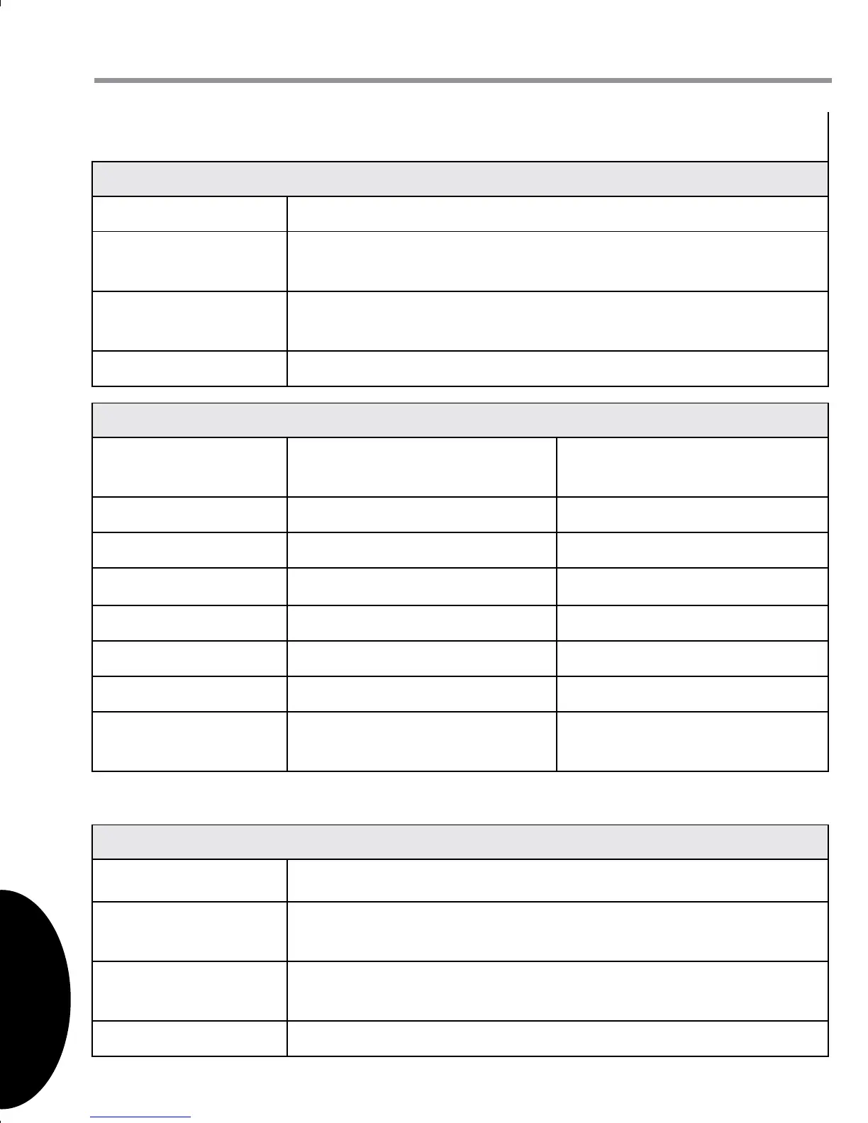
Alternate indoor unit to outdoor unit wiring: In some installations, only two wires
may be available for low voltage control wiring at the outdoor unit. If this is the case,
use the existing low voltage control wires and connect the 1, and 2 terminals as
shown in the gure below. Follow instructions below to wire the system.
° Install the supplied 40 VA transformer in the outdoor unit using the screws
provided. Align the holes in the transformer mounting bracket with the holes in
the sheet metal mounting panel and secure with screws.
° Connect one terminated end of the black 22” wire jumper to the 240VAC terminal
on the transformer (or 208VAC terminal if 208VAC system). Connect the other
terminated end of the wire jumper to L1 on the outdoor unit’s control.
° Connect the red 22” wire jumper to the 240VAC COM terminal on the transformer.
Connect the other end of the wire jumper to L2 on the outdoor unit’s control.
° Connect the terminated end of the red 14” wire jumper to the 24VAC terminal on
the transformer. Connect the other end to the “R” terminal on the included plug
connector.
° Connect the terminated end of the blue 14” wire jumper to the 24VAC COM
terminal on the transformer. Connect the other end to the “C” terminal on the
included plug connector.
he a t Pu m P /ai r Co n D i t i o n e r uS e r me n u S
Co n f i g u r a t i o n
Sub-menu Item Indication (for Display Only; not User Modiable)
Number of AC Stages
(CL STG)
Displays the number of air conditioning stages; applies to AC
and HP.
Number of HP Stages
(HT STG)
Displays the number of heat pump stages; applies to HP only.
AC Tonnage (TONS) Displays the air conditioning tonnage; applies to AC and HP.
Di a g n o S t i C S
Sub-menu Item Indication/User
Modiable Options
Comments
Fault 1 (FAULT #1) Most recent AC/HP fault For display only
Fault 2 (FAULT #2) Next most recent AC/HP fault For display only
Fault 3 (FAULT #3) Next most recent AC/HP fault For display only
Fault 4 (FAULT #4) Next most recent AC/HP fault For display only
Fault 5 (FAULT #5) Next most recent AC/HP fault For display only
Fault 6 (FAULT #6) Least recent AC/HP fault For display only
Clear Fault History
(CLEAR)
NO or YES Selecting “YES” clears the fault
history
iD e n t i f i C a t i o n
Sub-menu Item Indication (for Display Only; not User Modiable)
Model Number
(MOD NUM)
Displays the air conditioner or heat pump model number
Serial Number
(SER NUM)
Displays the air conditioner or heat pump serial number
(Optional)
Software (SOFTWARE) Displays application software revision
Touchscreen
Thermostat
Indoor
Board Te rminal
Connections
Outdoor
Board Te rminal
Connections
R
C
1
2
R
C
1
2
1
2
R
C
24VAC (Hot)
24VAC 230V
24VAC
(Common)
Data 1
Data 2
Outdoor 40VA
Tr ansformer
NOTE: Consecutively repeated faults are shown a maximum of 3 times.
° Dual Fuel Systems: It is highly recommended that the supplied 40VA transformer
be used in the outdoor unit. See Alternate indoor unit to outdoor unit wiring
for transformer wiring instructions.
° To maintain the UL rating on all AC and heat pump models the installing
contractor is required to use the low voltage wiring provided inside the control
panel when converting to the communicating control system.
 Loading...