EasyManuals Logo
Home>Connective Peripherals>Media Converter>ES-U Series

Connective Peripherals ES-U Series User Manual

Connective Peripherals ES-U Series
53 pages
To Next Page IconTo Next Page
To Previous Page IconTo Previous Page
Page #32 background imageLoading...
Page #32 background image
USB to Serial Converters Manual
Version 2.0
Document Reference No.: CP_000032 Clearance No.: CP#022
Copyright © Connective Peripherals Pte Ltd 32
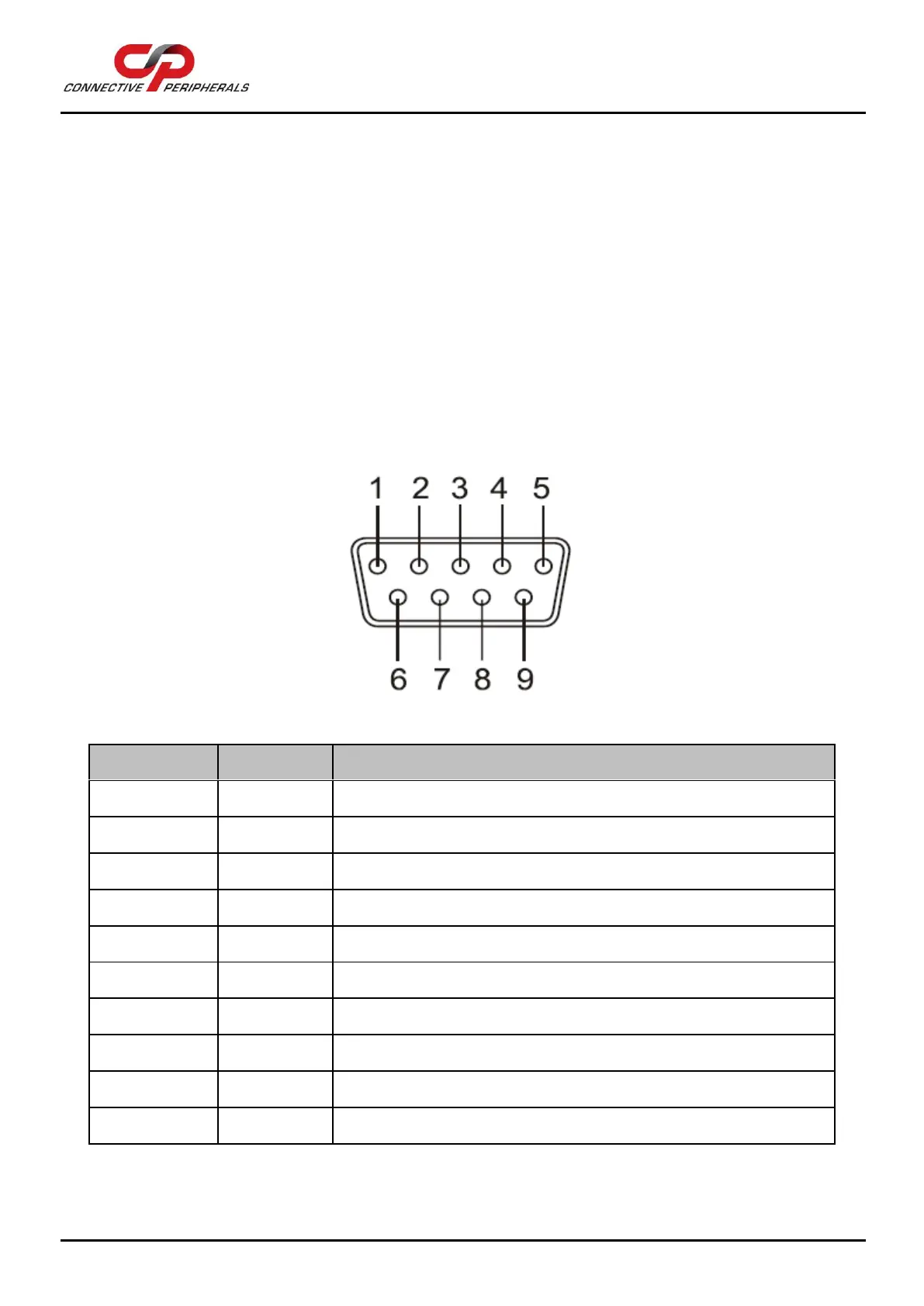
6 Connector Pinout Information
This section shows the connector pinouts used on the ES-U-xxxx-x converters.
6.1 RS-232
Signal Pin-
out
DB-9 Male connector
The RS232 ports are configured as Data Terminal Equipment (DTE), with a 9-contact D-Sub Pin connector.
Pin assignments are according to TIA/EIA-574 which formally defines the assignments for a COM port found
on many personal computers.
Figure 22 - DB-9 Male Connector Pin Numbers
Pin Number
Pin Type
Description
1
Input
DCD = Data Carrier Detect
2
Input
RXD = Receive Data
3
Output
TXD = Transmit Data
4
Output
DTR = Data Terminal Ready
5
Ground
GND = RS232 signal ground
6
Input
DSR = Data Set Ready
7
Output
RTS = Request To Send
8
Input
CTS = Clear To Send
9
Input
RI = Ring Indicator
Shield
Case Ground
Drain = typically connected to the host PC case
Table 11 - RS-232 Pin-Out for DB-9 connector

Table of Contents

Questions and Answers:

Question and Answer IconNeed help?

Do you have a question about the Connective Peripherals ES-U Series and is the answer not in the manual?

Connective Peripherals ES-U Series Specifications

General IconGeneral
BrandConnective Peripherals
ModelES-U Series
CategoryMedia Converter
LanguageEnglish

Related product manuals