USB to Serial Converters Manual
Version 2.0
Document Reference No.: CP_000032 Clearance No.: CP#022
Copyright © Connective Peripherals Pte Ltd 49
Appendix A - List of Figures and Tables
List of Figures
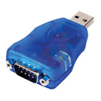
Figure 1 - DB-9 Male serial connectors. Some models also feature terminal blocks. ............................... 7
Figure 2 - ES-U-1032-RM (RJ45 connectors) is supplied with RJ45-to-DB-9 cables ................................ 8
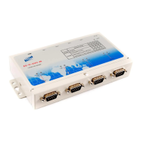
Figure 3 - Example of the Metal Rack-mount enclosure...................................................................... 8
Figure 4 - Examples of the Plastic and Metal (wall mountable) enclosures ............................................ 8
Figure 5 - Some models use a power adapter with barrel or terminal connector .................................... 9
Figure 6 - Rack-mount models have an internal supply with AC input connector ................................. 10
Figure 7 - ES-U-2xxx and ES-U-3xxx have DIP switches to select the serial mode .............................. 10
Figure 8 - ES-U-3008-RM has a set of jumpers for each port (one set circled) .................................... 11
Figure 9 Driver download from FTDI website ............................................................................. 13
Figure 10 User account control .................................................................................................. 13
Figure 11 Install Wizard initial window ........................................................................................ 14
Figure 12 Install Wizard – extracting files ................................................................................... 14
Figure 13 Install Wizard – ready to install ................................................................................... 14
Figure 14 Install Wizard – license agreement............................................................................... 15
Figure 15 Install Wizard – installing ............................................................................................ 15
Figure 16 Install Wizard – completion ......................................................................................... 16
Figure 17 – Windows update settings ............................................................................................ 17
Figure 18 – Windows installing driver in background ....................................................................... 18
Figure 19 - Hardware installed successfully .................................................................................... 18
Figure 20 - Device Manager after installing a converter with four ports .............................................. 19
Figure 21 - Advanced port settings dialog ...................................................................................... 20
Figure 22 - DB-9 Male Connector Pin Numbers ............................................................................... 32
Figure 23 -RJ45 Connector Pin Numbers ........................................................................................ 33
Figure 24 - RS-422 4 Wire Full Duplex ........................................................................................... 36
Figure 25 - RS-422 with Handshaking Signals Connected ................................................................. 37
Figure 26 - RS-485 Half Duplex Wiring .......................................................................................... 39
Figure 27 - RS-485 Full Duplex Wiring ........................................................................................... 42
Figure 28 – CDM Uninstaller – Initial window .................................................................................. 45
Figure 29 – Changing Product ID window ....................................................................................... 45
Figure 30 - CDM Uninstaller – Adding to list ................................................................................... 46
Figure 31 - CDM Uninstaller – Device removed ............................................................................... 46
List of Tables
Table 1 - Features of the ES-U-xxxx-x converters ............................................................................. 6
Table 2 - RS-422 & RS-485 Mode Configuration .............................................................................. 24
 Loading...