USB to Serial Converters Manual
Version 2.0
Document Reference No.: CP_000032 Clearance No.: CP#022
Copyright © Connective Peripherals Pte Ltd 42
Wiring Diagrams
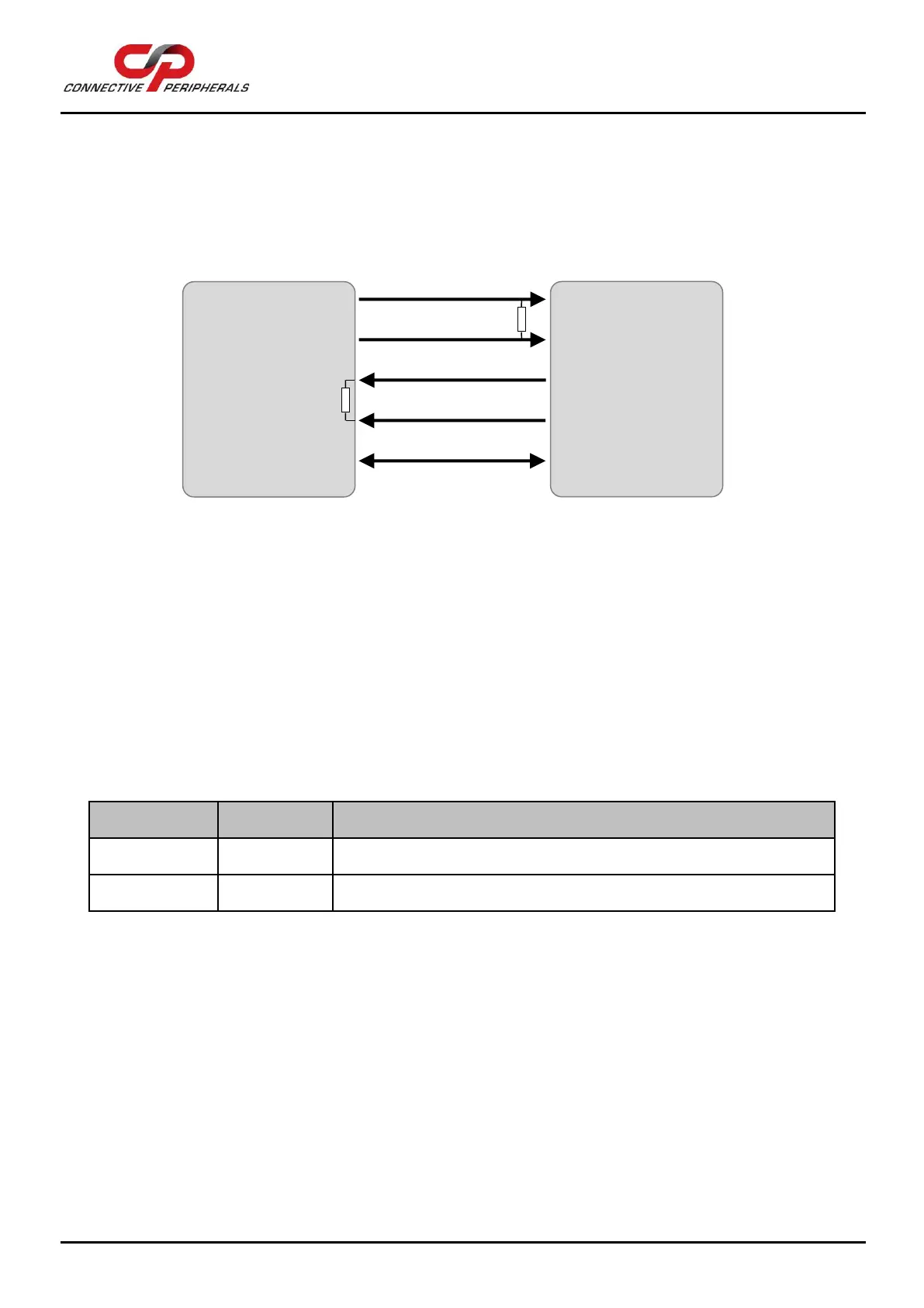
The following diagram shows an RS-485 full-duplex bus. The ES-U-xxxx-x has a built-in resistor for
terminating its RxD +/- input, which can be enabled using a jumper. The Tx +/- lines which are outputs
from the ES-U-xxxx-x would be terminated at the receiver at the other end of the bus as shown. Twisted
pair wires are required for each signal pair.
Figure 27 - RS-485 Full Duplex Wiring
6.5 5V Power Output (ES-U-1002-M only)
2-way Terminal Block
The table below shows the pin-out of the 2-way terminal block on the ES-U-1002-M converter. This provides
5V at up to 150mA for external devices. This power is supplied by the USB port of the computer.
 Loading...