(f) Set miter indicator on 0 ° position as shown.
STEP FOUR
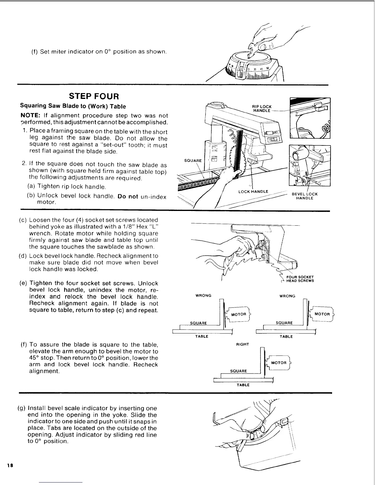
Squaring Saw Blade to (Work) Table
NOTE: If alignment procedure step two was not
oerformed, this adjustment cannot be accomplished.
1. Place a framing square on the table with the short
leg against the saw blade. Do not allow the
square to rest against a "set-out" tooth; it must
rest flat against the blade side.
2. If the square does not touch the saw blade as
shown (with square held firm against table top)
the following adjustments are required.
(a) Tighten rip lock handle.
(b) Unlock bevel lock handle. Do not un-index
motor.
SQUARE
\
RIPLOCK
HANDLE_
BEVELLOCK
HANDLE
(c) Loosen the four (4) socket set screws located
behind yoke as illustrated with a 1/8" Hex "L"
wrench. Rotate motor while holding square
firmly against saw blade and table top until
the square touches the sawblade as shown.
(d) Lock bevel lock handle. Recheck alignment to
make sure blade did not move when bevel
lock handle was locked.
(e) Tighten the four socket set screws. Unlock
bevel lock handle, unindex the motor, re-
index and relock the bevel lock handle.
Recheck alignment again. If blade is not
square to table, return to step (c) and repeat.
(f) To assure the blade is square to the table,
elevate the arm enough to bevel the motor to
45 ° stop. Then return to0 ° position, lower the
arm and lock bevel lock handle. Recheck
alignment.
HEAD SCREWS
WRONG WRONG
SQUARE
SQUARE [
I
TABLE TABLE
RIGHT
18
(g) Install bevel scale indicator by inserting one
end into the opening in the yoke. Slide the
indicator to one side and push until it snaps in
place. Tabs are located on the outside of the
opening. Adjust indicator by sliding red line
to 0° position.
 Loading...