assembly
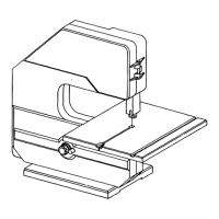
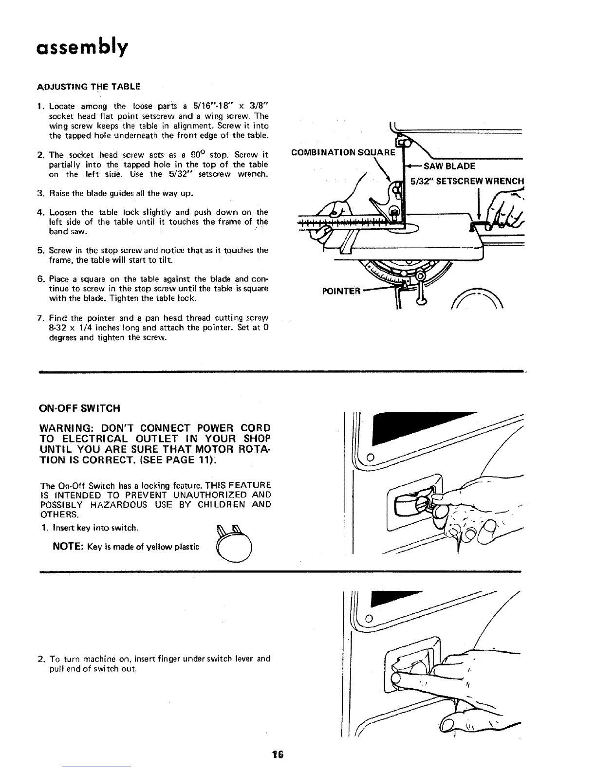
ADJUSTING THE TABLE
I. Locate among the loose parts a 5/16"-18" x 3/8"
socket head flat point setscrew and a wing screw. The
wing screw keeps the table in alignment. Screw it into
the tapped hole underneath the front edge of the table.
2. The socket head screw acts • as a 90 ° stop. Screw it
partially into the tapped hole in the top of the table
on the left side. Use the 5/32" setscrew wrench.
3. Raise the blade guides all the way up.
4. Loosen the table lock slightly and push down on the
left side of the table until it touches the frame of the
band saw.
5. Screw in the stop screw and notice that as it touches the
frame, the table will start to tilt.
6. Place a square on the table against the blade and con-
tinue to screw in the stop screw until the table is square
with the blade. Tighten the table lock.
7. Find the pointer and a pan head thread cutting screw
8-32 x 1/4 inches long and attach the pointer. Set at 0
degrees and tighten the screw.
COMBI NATI ON SQUARE
5/32"' SETSCREW WRENCH
ON-OFF SWITCH
WARNING: DON'T CONNECT POWER CORD
TO ELECTRICAL OUTLET IN YOUR SHOP
UNTIL YOU ARE SURE THAT MOTOR ROTA-
"rlON IS CORRECT. (SEE PAGE 11).
The On-Off Switch has a locking feature. THIS FEATURE
IS INTENDED TO PREVENT UNAUTHORIZED AND
POSSIBLY HAZARDOUS USE BY CHILDREN AND
OTHERS.
1. Insert key into switch.
NOTE: Key is made of yellow plastic
I I I i I I
2. To turn machine on, insert finger under switch lever and
pull end of switch out.
16
 Loading...