 Loading...
Do you have a question about the Craftsman 113.24350 and is the answer not in the manual?
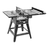
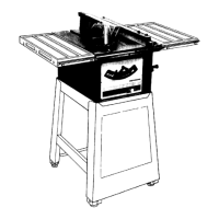
| Model Number | 113.24350 |
|---|---|
| Type | Table Saw |
| Blade Diameter | 10 inches |
| Arbor Size | 5/8 inch |
| Voltage | 120V |
| Amps | 13 Amps |
| Max Cut Depth at 90° | 3 inches |
| Rip Capacity | 24 inches |
| No Load Speed | 5000 RPM |
| Table Size | 20 x 26 inches |
Read the owner's manual carefully to learn its application, limitations, and specific potential hazards.
Ensure the tool is properly grounded using the 3-conductor cord and 3-prong plug for electrical safety.
Always wear safety goggles that comply with ANS Z87.1-1968, and a face or dust mask if operations are dusty.
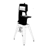
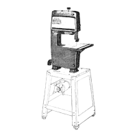
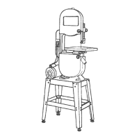
Ensures the band saw remains stable during operation to prevent tipping or movement during specific tasks.
Details necessary personal protective equipment and precautions for eyes, hands, face, ears, and body during operation.
Critical safety warnings and instructions to prevent severe injury, emphasizing reading the manual and proper tool usage.
Instructions for safely connecting the power source, including grounding and proper outlet usage.
Procedure to verify the motor rotates counterclockwise when viewed from the pulley end before operation.
Instructions for assembling the band saw/sander, starting with mounting and installing the sawdust elbow.
Detailed steps for correctly installing the table onto the band saw/sander unit.
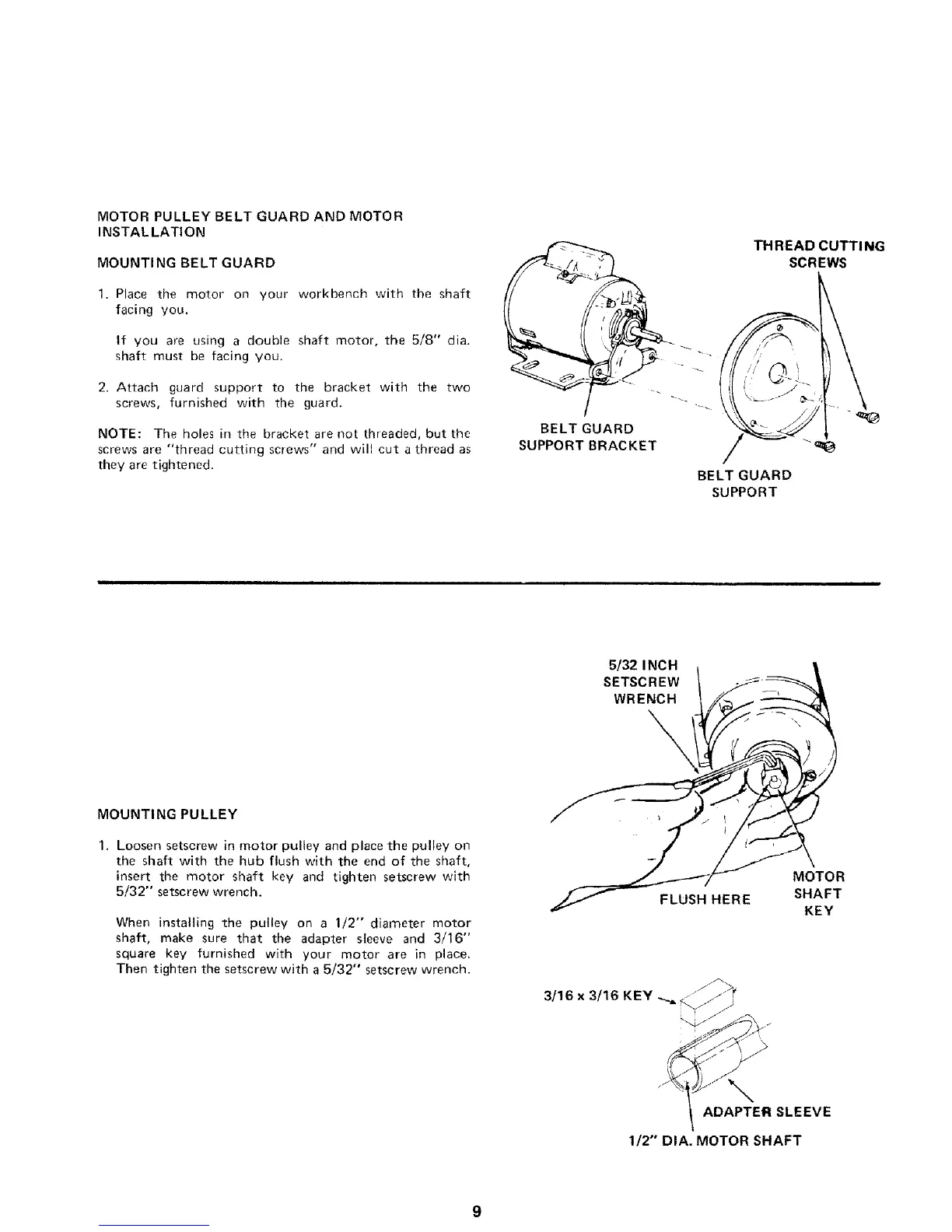
Guide for installing the motor pulley, belt guard, and motor onto the band saw/sander.
Procedure to verify the motor rotates counterclockwise when viewed from the pulley end before operation.
Instructions for securely mounting the motor onto the band saw/sander base.
Steps for attaching the belt guards and routing the drive belt correctly.
Instructions for installing the band saw blade, including tensioning and guide adjustments.
Procedure for adjusting the table to be square with the blade and setting the tilt stop.
Explanation of the on-off switch operation, including its locking feature and key usage.
Instructions for installing the motor cord clamp to secure the power cord.
Visual guides and explanations of the various adjustment points and diagrams for the band saw/sander.
Instructions on how to use the tension adjusting knob to set the correct blade tension for operation.
Details on using tension scales to determine the correct blade tension based on blade width.
Procedures for adjusting and setting the tilt angle of the band saw table for angled cuts.
Instructions for setting and aligning the guide bar parallel to the blade for proper operation.
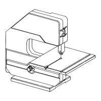
Steps for installing the sanding attachment, including blade removal and guide adjustments.
Guidance on performing sawing operations, including workpiece handling and blade selection.
Instructions for using the sanding feature, emphasizing practice and proper workpiece handling.
Procedures for cleaning and maintaining the band saw tires, and when to replace them.
Routine cleaning instructions for the band saw, including the table, guides, and bearings.
Guidance on cleaning sawdust from the motor and handling power cord issues.
Information on lubrication requirements for ball bearings and guide rods.
Identifies common problems with the band saw/sander, their probable causes, and recommended remedies.
A list of optional accessories available for purchase to enhance the band saw/sander's functionality.
Detailed listing of parts for Figure 1 of the band saw/sander, including key numbers and descriptions.
Detailed listing of parts for Figure 2 of the band saw/sander, including key numbers and descriptions.