unpacking and checking contents
UNPACKING AND CHECKING CONTENTS .....
ASSEMBLY ...........................
Mounting Band Saw/Sander on Recommended
Craftsman Floor Base ................... 7
Installing Sawdust Elbow ................. 7
Installing Table ....................... 8
Motor Pulley Belt Guard and Motor Installation.. 9
Check Motor Rotation .................. 10
Mounting Motor ...................... 10
Attaching Belt Guards ................... 11
Installing The Blade .................... 12
Adjusting The Table .................... 16
On-0ff Switch ........................ 16
GETTING TO KNOW YOUR BAND
SAW/SANDER ......................... 18
Adjustment Diagrams ................... 18
Tension Adjustment Knob ................ 18
Tension Scales ........................ 18
CONTENTS
6
7
Table Tilting ......................... 18
Blade Guide Adjustment ................. 18
Lateral Guide Adjustment ................ 18
Blade Thrust Bearing Adjustment ........... 18
Guide Bar Lock Screw .................. 18
Guide Bar ........................... 19
Installing Sanding Attachment ............. 19
BASIC BAND SAW/SANDER OPERATION ...... 21
Sawing ............................. 21
Sanding ............................ 21
MAINTENANCE ........................ 22
Tires .............................. 22
General ............................ 22
Motor ............................. 22
Lubrication .......................... 22
TROUBLE SHOOTING ................... 23
Recommended Accessories ................ 23
REPAIR PARTS ........................ 24
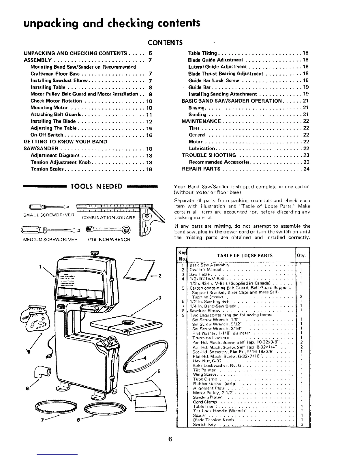
TOOLS NEEDED
SMALL SCREWDRIVER COMBINATION SQUARE
MEDIUM SCREWDRtVE R 7/16 INCH WRENCH
1\
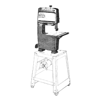
Your Band Saw/Sander is shipped complete in one carton
(without motor or floor base).
Separate all parts from packing materials and check each
item with illustration and "Table of Loose Parts." Make
certain all items are accounted for, before discarding any
packing material.
If any parts are missing, do not attempt to assemble the
band saw, plug in the power cord or turn the switch on until
the missing parts are obtained and installed correctly.
:,..eyj;K] TABLE OF LOOSE PARTS Qty.
No.I
1 Basic Saw Assembly ................. t
2 Owner's Manual 1
3 Saw Table ...................... !
4 1/2x 52-1n.V-Bek .................. !
1/2 x 43-1n. V-Belt (Supplied in Canada) ...... 1
5 Carton containing Belt Guard, Belt-Guard Support,
Support Bracket, three Clips and three Self
Tapping Screws 2
6 1/2-h% Sanding Belt 1
7 1/4-1n. Band=Saw Blade ............... 1
8 Sawdust Elbow ................... 1
9 Two Bags containing the following items:
Set Screw Wrench, 1/8" . ............ 1
Set Screw Wrench, 5/32" . ........... 1
Set Screw Wrench, 3/16" . ........... 1
Flat Washer, t-!/8" diameter ........... 1
Trunnion Looknut ................. 1
Pa_lHd, Mach. Screw, Self Tap, 10-32x3/8". .... 2
Pan Hd. Mach. Screw, Self Tap, 8-32x 1/4" . .... 2
Soc-Hd, Setscrew, Flat Pt. 5/16-18x3/8" . ..... 1
Flat-Hd. Macb. Screw, 6-32x7/16". ........ 1
He× Nut, 6-32 ................... 1
Spilt Lockwasher, No. 6 .............. 1
Tilt Pointer .................... 1
Wing Screw ....................... 1
Tube Clamp .................... '_
Rubber Gasket (stripl ............... !
Alignment Plate .... ". ............. 1
Motor Pulley, 2-I/2", ............... !
Banding Platen .................. 1
Cord Clamp !
Table Insert 1
Tilt Lock Handle (Wrench) 1
Spacer ....................... 1
Blade Tension Knob .............. 1
Switch Key .................... 2
 Loading...