15
The vent pipe outlet is sized to accept 2” pipe. Secure vent
pipe directly into the furnace tting with the appropriate
glue. Alternately, a small section of 2” pipe may be glued
in the furnace socket and a rubber coupling installed to
allow removal for future service. Piping should be routed in
a manner to avoid contact with refrigerant lines, metering
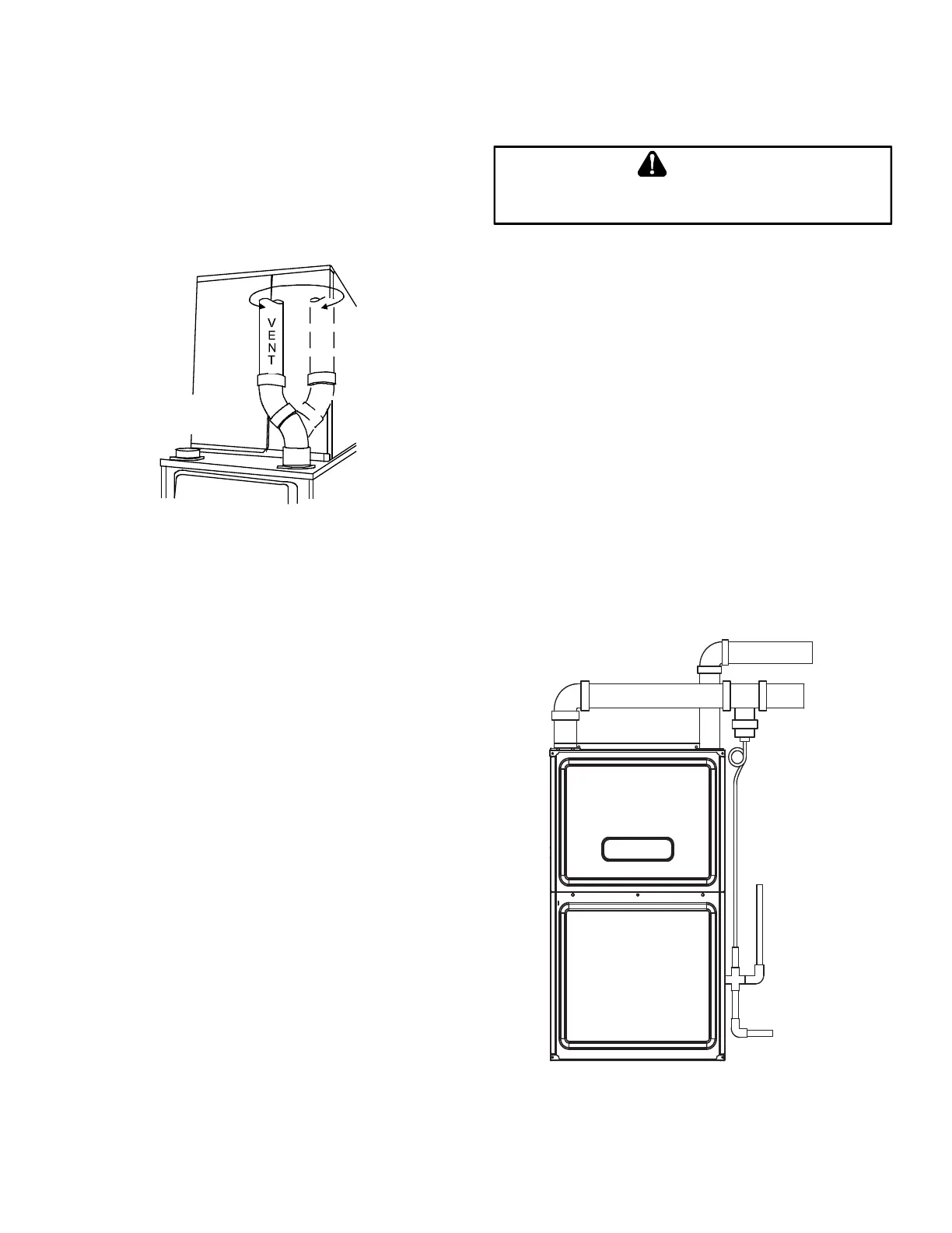
devices, condensate drain lines, etc. If necessary,
clearances may be increased by creating an oset using
two 45° elbows (Figure 7).
If the furnace is being installed without a combustion air
pipe, a 90° elbow should be used on the combustion air
intake to guard against blockage.
On up ow / horizontal models, secure the combustion
air intake pipe to the air intake coupling using a rubber
coupling supplied with the furnace. The rubber coupling
may be omitted by inverting the intake coupling and gluing
pipe directly to it. Piping may also be glued to the intake
coupling in its original position by using a plastic coupling.
On counterow units secure the combustion air intake
pipe to the air intake coupling using the rubber coupling
and worm gear hose clamps provided with the unit. The
counterow rubber coupling allows service removal of air
intake piping internal to the furnace blower compartment.
The combustion air intake pipe can also be secured
directly to the counterow unit air intake pipe coupling.
The RF000142 coupling (Figure 9) can be secured
directly to the furnace intake coupling if condensation/
rain water is a concern. If the RF000142 is used on the
combustion air inlet, it must be installed with the arrow
pointing up. It should be noted, the combustion air will
actually be moving in a direction opposite of the arrow
on the RF000142 coupling. It must have a eld supplied,
trapped drain tube free-draining to a proper condensate
disposal location. A loop in the drain tube can serve as a
trap. The unused RF000142 drain tting must be capped.
A eld supplied tee installed in the intake pipe is also an
acceptable method of catching condensation. It must have
a eld supplied, trapped drain tube or pipe, free-draining to
a proper condensate disposal location. A loop in the drain
tube can serve as a trap.
E
SHEET
HOLES
BE
SHARP
SE
AS
A
PRECAUTION
HOLE
When installing a furnace horizontally with the left side
down, alternate ue and combustion air pipe connections
may be used. This method allows the ue and combustion
air piping to be run vertically through the side of the
furnace (facing up in horizontal left). The alternate vent
location is the 3” hole directly in line with the induced draft
blower outlet.
When using the horizontal alternate vent conguration, you
must use the RF000142 vent drain kit. See Figures 8-11 &
follow steps below.
 Loading...


