23
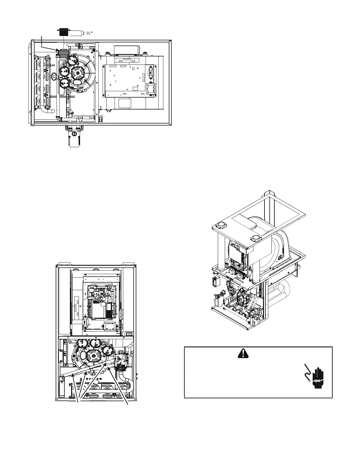
Insert flange. Cut 2 ½” long.
R 000142F
The furnace drain may exit the right or left side of the
furnace cabinet (left side preferred) Trap and factory
installed hoses remain as shipped if the drain will exit
the left side of the cabinet. Draining from the right side
requires relocation of the trap to outside the cabinet.
1. Install a eld supplied rubber coupling secured with
a 1 1/4” clamp to enable removing the trap for future
cleaning. Alternately, a PVC tting may be glued on
the trap outlet.
2. Install drain per local and National codes.
1. Removing the gas manifold assembly will provide
better access when re-locating the trap. To remove
the gas manifold, remove the four screws that fasten
the gas manifold assembly to the bracket.
2. Remove hose clamps and hoses from trap.
3. Remove trap.
4. (Draining the Vent Elbow) Insert the non-grommet
end hose #10 into the cabinet back drain hole. Insert
a coupling into the drip leg of the vent-drain elbow
and secure with a silver clamp. Secure hose #10 on
vent - drain elbow barb tting with a silver clamp.
5. (Draining the Collector Box) Insert non-grommet
end of hose #9 into the cabinet front drain hole
and secure on collector box drain port with a silver
clamp.
6. Mate the drain trap inlets to the hoses and secure
with silver clamps.
7. Line up the trap mounting holes with the pre-drilled
holes in the furnace and secure with 2 screws
removed in step 2.
8. Refer to Field Supplied Drain section for instructions
on eld supplied / installed drain on outlet of furnace
trap.
!
T
O
AVOID
PERSONAL
INJURY
OR
DEATH
DUE
TO
ELECTRICAL
SHOCK
,
DISCONNECT
ELECTRICAL
OR
ANY
ELECTRICAL
 Loading...


