37
1. Turn OFF gas to furnace at the manual gas shuto
valve external to the furnace.
2. Connect a calibrated manometer (or appropriate gas
pressure gauge) at either the gas valve inlet pressure
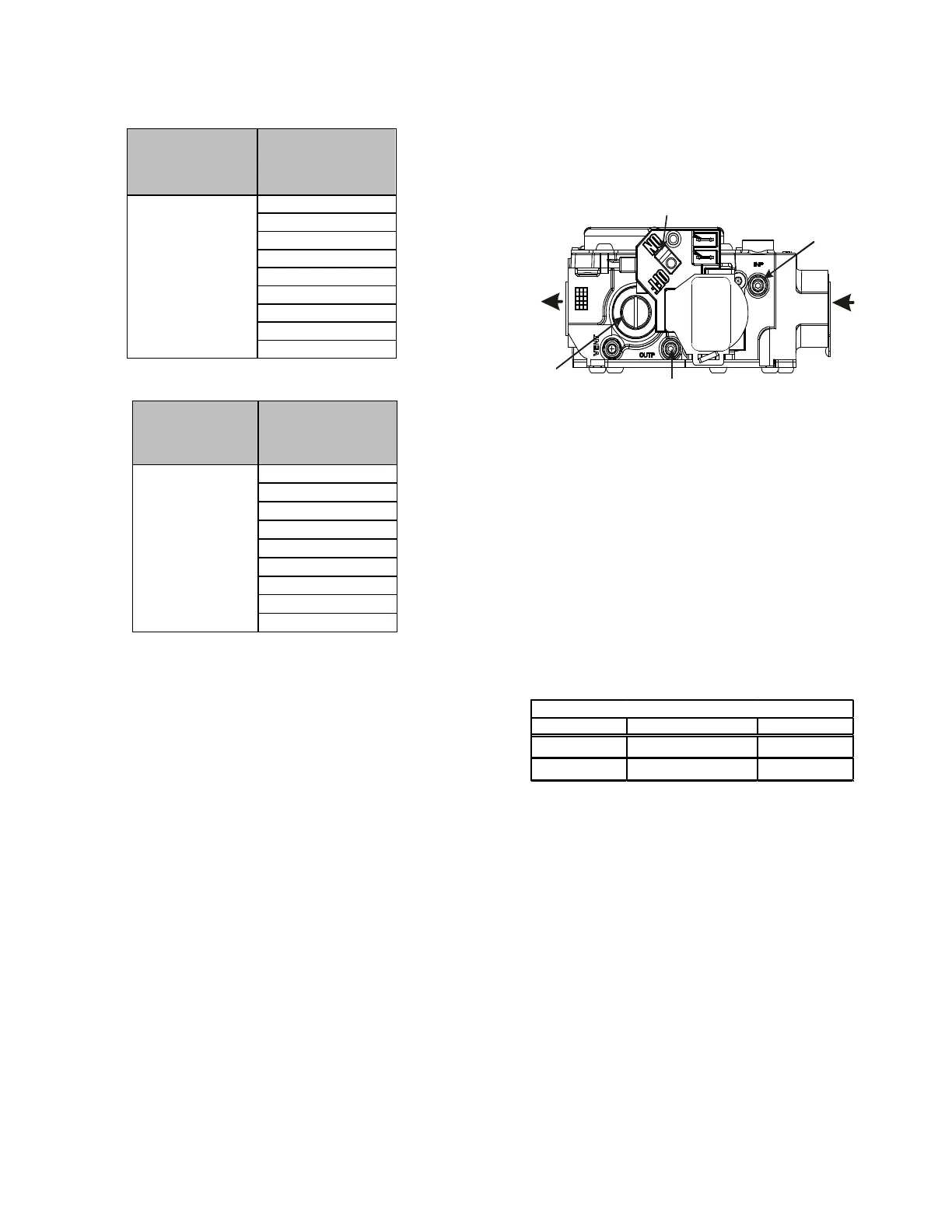
tap or the gas piping drip leg. See White-Rodgers
36J22 gas valve gure for location of inlet pressure
tap.
Gas Valve ON/OFF Selector Switch
Outlet Pressure
Inlet Pressure
Regulator
Cover Screw
0151K00000S.
3. Turn ON the gas supply and operate the furnace and
all other gas consuming appliances on the same gas
supply line.
4. Measure furnace gas supply pressure with burners
ring. Supply pressure must be within the range
specied in the table.
Natural 3.2 - 3.8" w.c. 3.5" w.c.
Propane 9.7 - 10.3" w.c. 10.0" w.c.
If supply pressure diers from table, make the necessary
adjustments to pressure regulator, gas piping size, etc.,
and/or consult with local gas utility.
5. Turn OFF gas to furnace at the manual shuto valve
and disconnect manometer. Reinstall plug before
turning on gas to furnace.
6. Turn OFF any unnecessary gas appliances stated in step.
3. When the center switch is pressed, the current
displayed speed will be selected, and control will
apply the newly selected speed in next cooling call.
THERMOSTATCALL AVAILABLESPEEDS
Y/Y1
F01
F02
F03
F04(DEFAULT)
F05
F06
F07
F08
F09
THERMOSTATCALL AVAILABLESPEEDS
Y2
F01
F02
F03
F04
F05(DEFAULT)
F06
F07
F08
F09
1. Set the thermostat to the lowest setting. The
integrated control will close the gas valve and
extinguish ame. Following a 15 second delay, the
induced draft blower will be de-energized. After
the blower o delay time expires, the blower de-
energizes.
2. Remove the burner compartment door and move
the furnace gas valve manual control to the OFF
position.
3. Close the manual gas shuto valve external to the
furnace.
4. Replace the burner compartment door.
The line pressure supplied to the gas valve must be within
the range specied below. The supply pressure can be
measured at the gas valve inlet pressure tap or at a hose
tting installed in the gas piping drip leg. The supply
pressure must be measured with the burners operating.
To measure the gas supply pressure, use the following
procedure.
 Loading...


