27
!
T
O
AVOID
PERSONAL
INJURY
OR
DEATH
DUE
TO
ELECTRICAL
SHOCK
,
DISCONNECT
ELECTRICAL
OR
ANY
ELECTRICAL
This furnace can be used in conjunction with a heat pump
in a fossil fuel application. A fossil fuel application refers to
a combined gas furnace and heat pump installation which
uses an outdoor temperature sensor to determine the most
cost ecient means of heating (heat pump or gas furnace).
A heat pump thermostat is required to properly use a
single-stage furnace in conjunction with a heat pump.
Refer to the fossil fuel kit installation instructions for
additional thermostat requirements.
Strictly follow the wiring guidelines in the fossil fuel kit
installation instructions. All furnace connections must be
made to the furnace two-stage integrated control module
and the “FURNACE” terminal strip on the fossil fuel control
board.
Two furnaces of the same model may be twinned. The
integrated control board has a 3/16” terminal labeled
“TWIN” located beside the low voltage thermostat
connection strip. Twinning allows simultaneous operation
of two furnaces and forces the indoor blower motors of
each furnace to operate synchronously into a common
duct system. Using the twinning function will require only
eld installed wiring with no external kits or parts. The
staging and speed tap options must be set the same on
both furnaces.
1. Measure resistance between the neutral (white)
connection and one of the burners.
Resistance should measure 10 ohms or less.
This furnace is equipped with a blower door interlock
switch which interrupts unit voltage when the blower door
is opened for servicing. Do not defeat this switch.
maintenance.
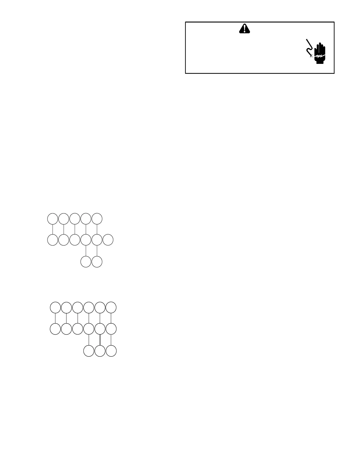
Low voltage connections can be made through either the
right or left side panel. Thermostat wiring entrance holes
are located in the blower compartment. The following
gure shows connections for a “heat/cool system”.
This furnace is equipped with a 40 VA transformer to
facilitate use with most cooling equipment. Consult the
wiring diagram, located on the blower compartment door,
for further details of 115 Volt and 24 Volt wiring.
Y
C
Y
C
G
R
W
Y2
Y/Y1
C
G
R
W
ROOM THERMOSTAT
INTEGRATED FURNACE
CONTROL MODULE
REMOTE COOLING UNIT
(SINGLE STAGE)
Y1
C
Y1C
G
R
W
Y2
Y/Y1
C
G
R
W
ROOM THERMOSTAT
INTEGRATED FURNACE
CONTROL MODULE
REMOTE COOLING UNIT
(TWO STAGE)
Y2
Y2
 Loading...


