Operating instructions
8
Daikin RoCon
Daikin Control unit
008.1543999_00 – 03/2017 – EN
3 x Operation
3Operation
3.1 General
3.2 Display and operating elements
3.2.1 Display
All operating steps are supported by corresponding displays on a
coloured backlit plain text display.
The menu guidance can be displayed 7 languages (see
chap.
3.4.8).
The colour of the backlighting indicates the operational status
and the operating mode:
DANGER!
If electrical components come into contact with
water, this can cause an electric shock as well
as cause potentially fatal burns or injuries.
● The displays and the keys of the control unit
must be protected against the effects of
moisture.
● To clean the control unit, use a dry cotton
cloth. Using aggressive cleaning agents
and other liquids can cause damage to
equipment or lead to an electric shock.
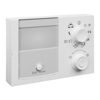
1 Clear text display
2 Setting: Configuration
3 Setting: Remote Param
4 Rotary switch
5 Setting: Info
6 Setting: Operating Mode
7 Setting: Set Temp Day
8 Setting: Set Temp Night
9 Setting: DHW Set Temp
10 Rotary button
11 Setting: DHW Reheating
12 Setting: Time Program
13 Exit key
Fig. 3-1 Arrangement of display and operating elements
Faults are generally indicated by an error code and a
clear text error message on the display.
For troubleshooting instructions, see chap. 7.
White: Standard lighting, normal operating display.
Red: Error status; depending on the type of error, the
Daikin heat generator continues to operate with
restrictions.
Green: Operating mode with operator authorisation.
Blue: Operating mode with expert authorisation.
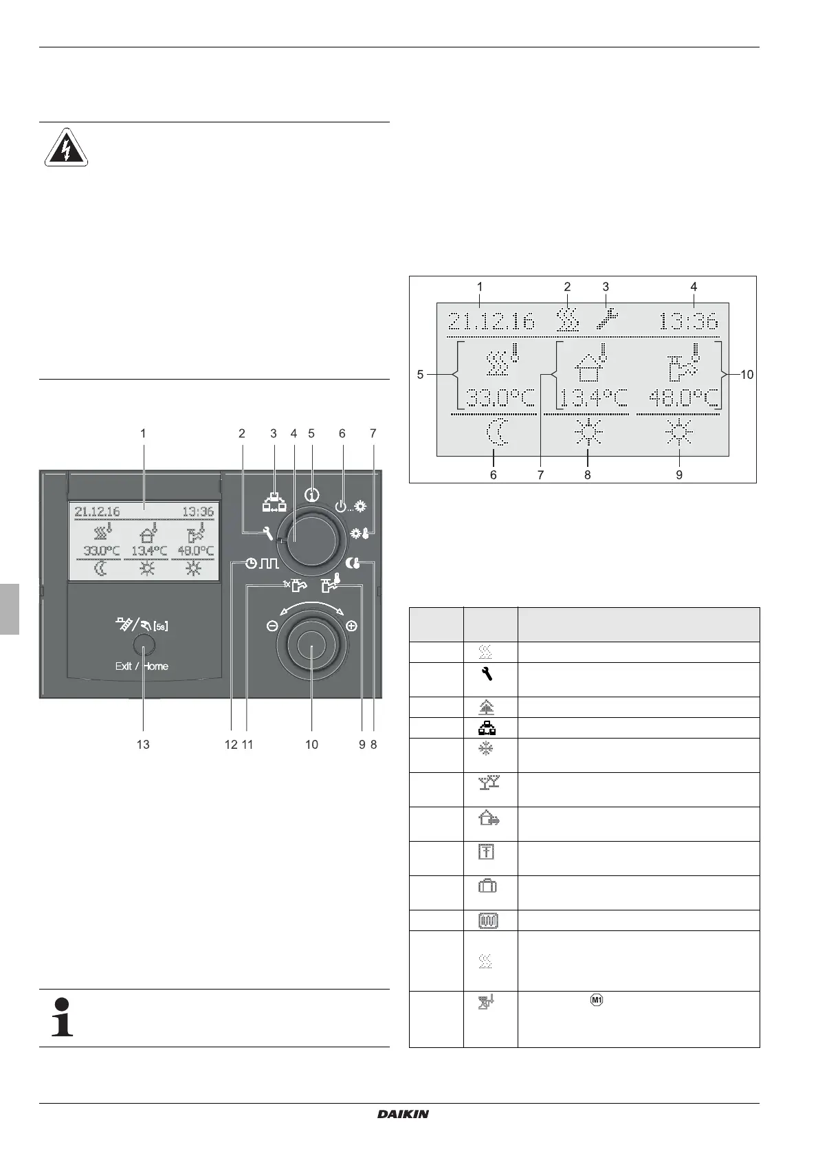
1 Display date
2 Burner activity status
3 Expert login display
4 Time display
5 Current T-HS
6 Heating circuit status
7 Current outside temperature
8 Active operating mode
9 Hot water generation status
10 Current storage temperature
Fig. 3-2 Display of the control unit - standard display
Item
fig. 3-2
Icon Explanation
2 Heat requirement active
3 Expert access rights active (see
chap.
3.6.1)
2 / 3 Air purge active (see chap. 3.6.4)
2 / 3 Terminal function active (see chap. 3.4.9)
2 / 3 Frost protection function active (see
chap.
3.6.11)
2 / 3 Temporary time program "Party" active (see
chap. 3.4.7)
2 / 3 Temporary time program "Away" active
(see chap.
3.4.7)
2 / 3 Temporary time program "Holiday" active
(see chap. 3.4.7)
2 / 3 Temporary time program "Vacation" active
(see chap. 3.4.7)
2 / 3 Screed program active (see chap. 3.6.7)
5 Direct heating circuit
– During normal operation, the current T-
HS t
V1
is displayed underneath.
5 Mixer circuit
The current T-HS of the assigned heating
circuit is displayed underneath.
 Loading...