SiUS091133 Check
Service Diagnosis 142
5. Check
5.1 Thermistor Resistance Check
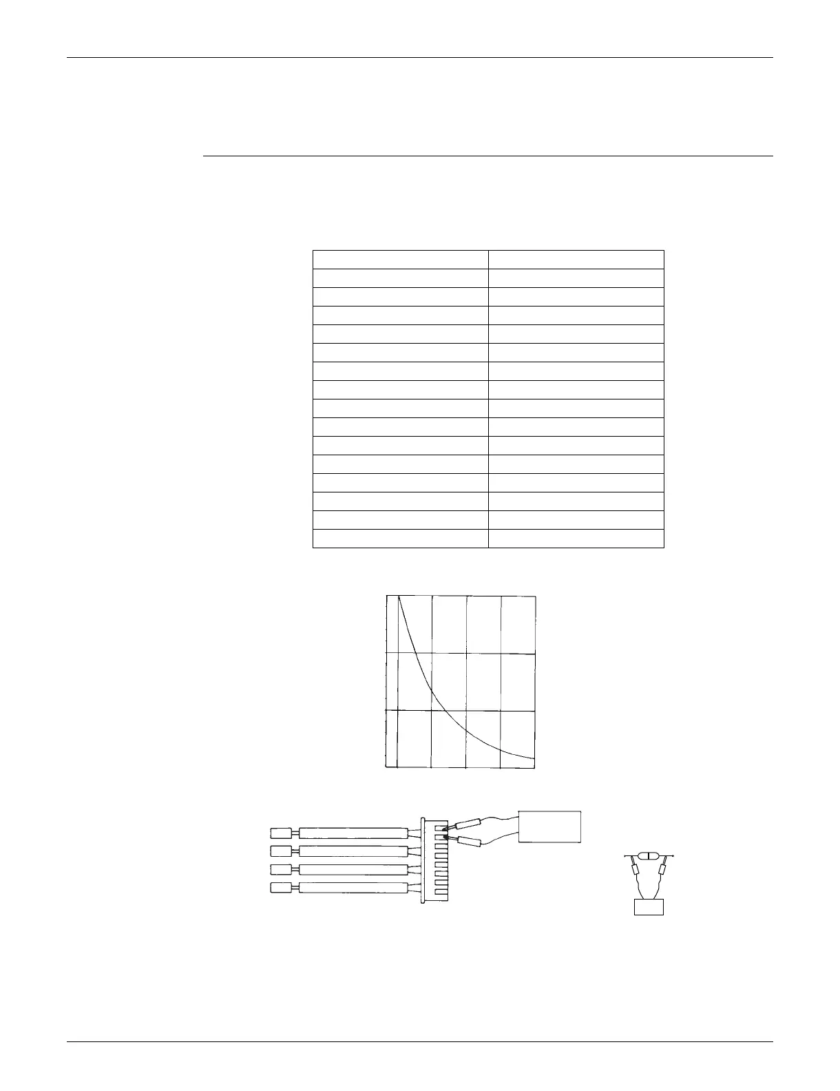
Check No.01 Disconnect the connectors of the thermistors from the PCB, and measure the resistance of each
thermistor using tester.
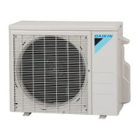
The relationship between normal temperature and resistance is shown in the table and the graph
below.
The data is for reference purpose only.
The room temperature thermistor is directly mounted on the display PCB. Remove the display
PCB from the control PCB to measure the resistance.
When the indoor heat exchanger thermistor is soldered on the PCB, remove the thermistor and
measure the resistance.
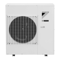
Temperature (°C / °F) Resistance (k)
–20 / –4 197.8
–15 / 5 148.2
–10 / 14 112.1
–5 / 23 85.60
0 / 32 65.93
5 / 41 51.14
10 / 50 39.99
15 / 59 31.52
20 / 68 25.02
25 / 77 20.00
30 / 86 16.10
35 / 95 13.04
40 / 104 10.62
45 / 113 8.707
50 / 122 7.176
(R25°C (77°F) = 20 k, B = 3950 K)
(kΩ)
150
100
50
–15 0 15 30 45
(R14467)
5 32 59 86 113
(˚C)
(˚F)
Tester
Resistance range
(R11906)
 Loading...