19 | Electrical installation
Installer and user reference guide
105
RXMLQ8 + RXYLQ10~14T7Y1B*
VRV IV system air conditioner
4P543427-1A – 2020.10
Field piping can be routed from front or bottom of the unit (going left or right).
Refer to "To route the refrigerant piping"[482].
▪ Be sure to follow the limits below. If the unit-to-unit cables are beyond these
limits, it may result in malfunction of transmission:
- Maximum wiring length: 1000m.
- Total wiring length: 2000m.
- Maximum inter unit wiring length between outdoor units: 30m.
- Transmission wiring to cool/heat selector: 500m.
- Maximum number of branches: 16.
▪ Maximum number of independent interconnectable systems: 10.
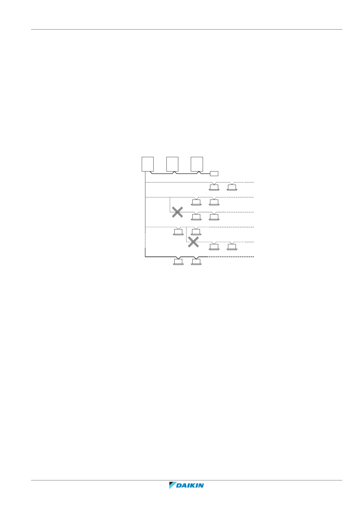
▪ Up to 16 branches are possible for unit-to-unit cabling. No branching is allowed
after branching (see figure below).
a Outdoor unit
b Indoor unit
c Main line
d Branch line 1
e Branch line 2
f Branch line 3
g No branch is allowed after branch
h Central user interface (etc...)
A Outdoor/indoor transmission wiring
B Master/slave transmission wiring
For the above wiring, always use vinyl cords with 0.75 to 1.25mm
2
sheath or cables
(2-core wires). (3-core wire cables are allowable for the cooler/heater changeover
user interface only.)
19.1.4 Guidelines when knocking out knockout holes
▪ To punch a knockout hole, hit on it with a hammer.
▪ After knocking out the holes, we recommend removing any burrs and paint the
edges and areas around the holes using repair paint to prevent rusting.
▪ When passing electrical wiring through the knockout holes. prevent damage to
the wires by wrapping the wiring with protective tape, putting the wires through
field supplied protective wire conduits at that location, or install suitable field
supplied wire nipples or rubber bushings into the knockout holes.

 Loading...