18 | Piping installation
Installer and user reference guide
81
RXMLQ8 + RXYLQ10~14T7Y1B*
VRV IV system air conditioner
4P543427-1A – 2020.10
If Then
>2m
a To indoor unit
b Piping between outdoor units
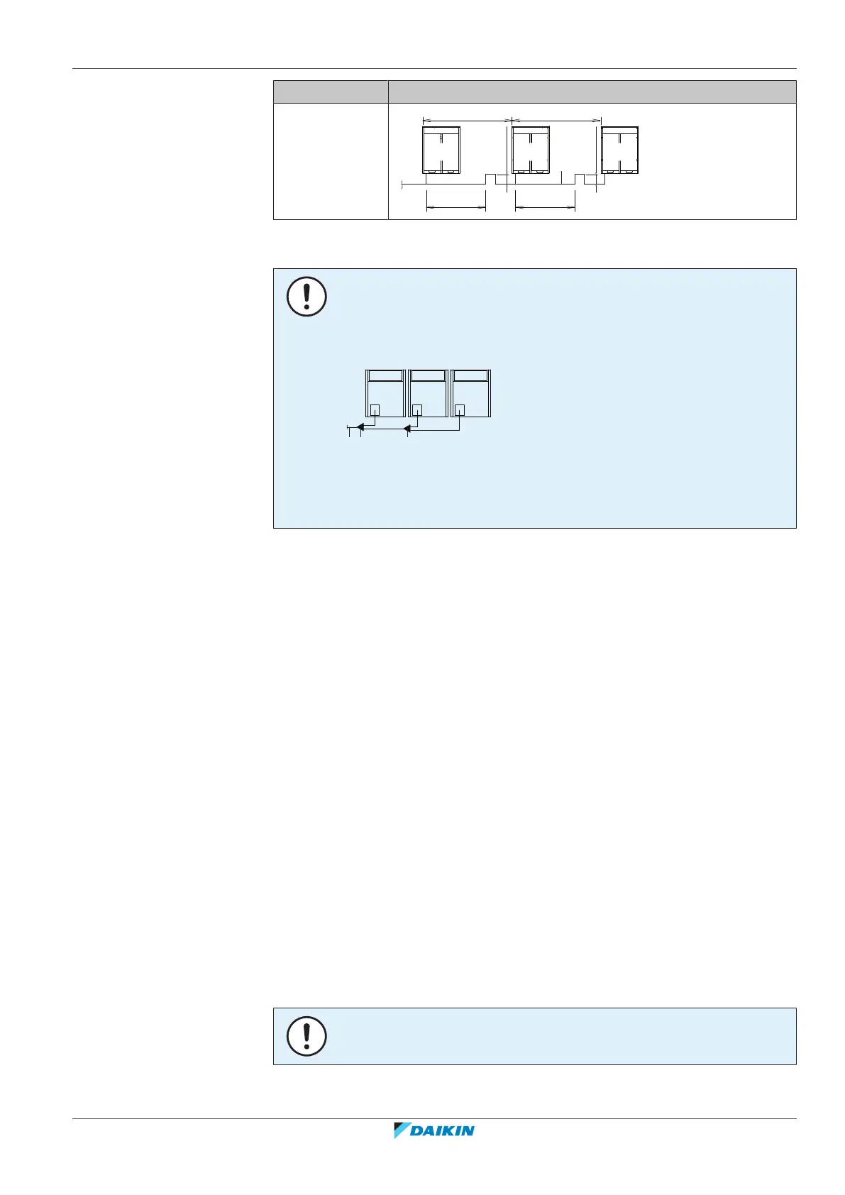
NOTICE
There are restrictions on the refrigerant pipe connection order between outdoor
units during installation in case of a multiple outdoor unit system. Install according to
following restrictions. The capacities of outdoor units A, B and C must fulfill the
following restriction conditions: A≥B≥C.
a To indoor units
b Outdoor unit multi connecting piping kit (first branch)
c Outdoor unit multi connecting piping kit (second branch)
18.2 Connecting the refrigerant piping
18.2.1 About connecting the refrigerant piping
Before connecting the refrigerant piping, make sure the outdoor and indoor units
are mounted.
Connecting the refrigerant piping involves:
▪ Routing and connecting the refrigerant piping to the outdoor unit
▪ Protecting the outdoor unit against contamination
▪ Connecting the refrigerant piping to the indoor units (see the installation manual
of the indoor units)
▪ Connecting the multi-connection piping kit
▪ Connecting the refrigerant branching kit
▪ Keeping in mind the guidelines for:
- Brazing
- Using the stop valves
- Removing the pinched pipes
18.2.2 Precautions when connecting the refrigerant piping
NOTICE
Make sure the field piping and connections are NOT subjected to stress.

 Loading...