Tension mode setup
Provided...
▪ The touring cart is loaded and prepared for Tension mode as
described in Þ "Manually loading for Tension mode"
on page 37) and in position.
▪ The load beam has already been attached to the flying frame,
as described in the previous section Þ "Attaching the load
beam to the flying frame" on page 45.
▪ The safety chain has already been attached to the flying frame,
as described in Þ Chapter 3.14 "Secondary safety"
on page 31.
... proceed as follows:
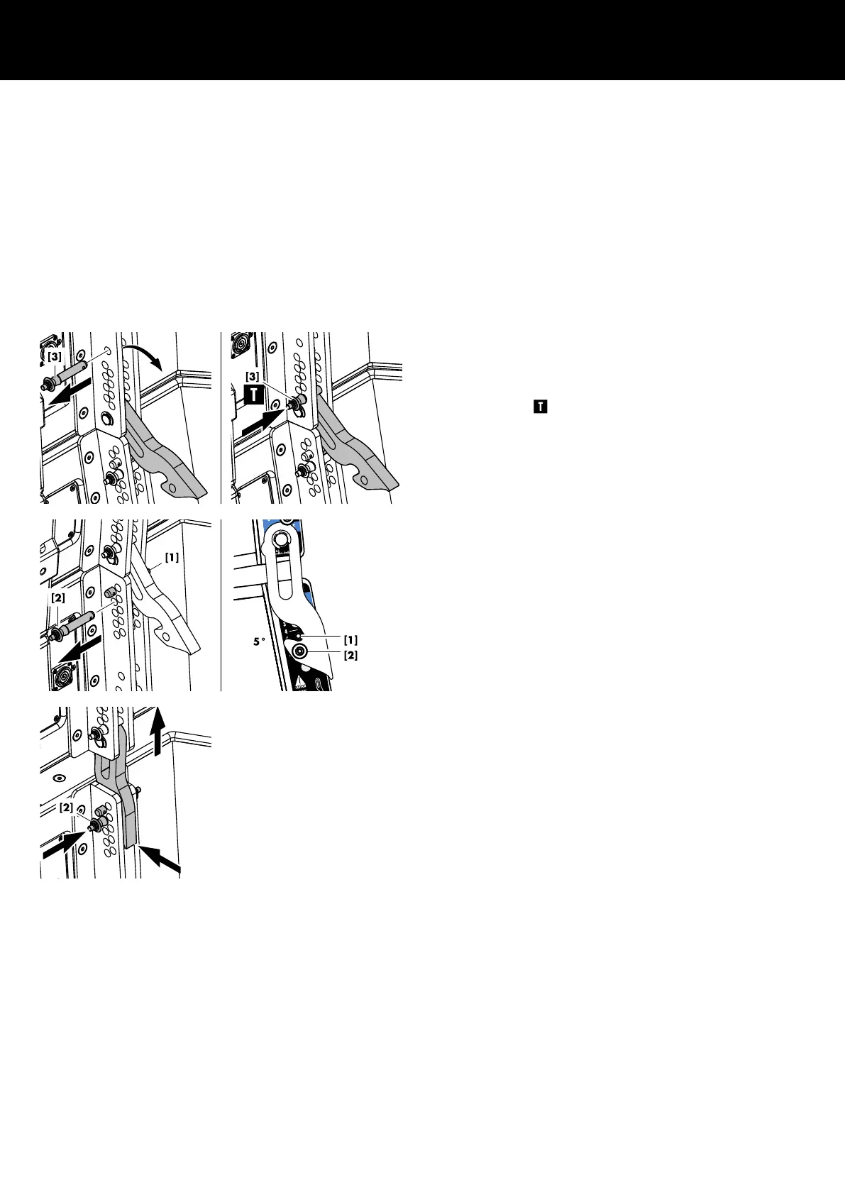
1. Preparing the first assembly
1. For the upper three cabinets, release Locking pin [3] and fold
out the Splay link.
2. Reinsert Locking pin [3] to the lowest hole position of the
bottom hole grid to fix the Splay link in its Tension mode
position (Þ ).
3. On every cabinet, release Locking pin [2].
4. On the top hole index, preset the splay angles according to
your ArrayCalc project using Locking pin [1] (See also
Þ Chapter 2 "SL-Series rigging modes - 2 in 1" Þ "Tension
mode principle" on page 9).
5. Lift the assembly including the cart until all Splay links have
engaged.
6. Reinsert Locking pin [2] (Safety pin) on all cabinets.
7 Tension mode setup
d&b SL-Series Rigging manual 1.10 en54
 Loading...