33
MG.10.J4.02 – VLT is a registered Danfoss trade mark
VLT
®
5000 SyncPos option
NB!
The scaling of the FFVEL parameter is de-
pendent on the correct setting of the maxi-
mum reference (VLT parameter #205) as well as the
SyncPos parameters VELMAX (1) and ENCODER
(2). A higher setting of VLT parameter #202 requires
a higher setting of the VELMAX parameter since
they must maintain the same ratio.
Acceleration Feed-forward FFACC (37)
The
Acceleration feed-forward factor Acceleration feed-forward factor
Acceleration feed-forward factor Acceleration feed-forward factor
Acceleration feed-forward factor is multiplied
with the 2nd derivative of the setpoint position (the
acceleration of the setpoint) and the result is
added to the control signal. This feature should be
used to compensate for the torque used to accele-
rate/decelerate the system inertia.
NB!
Scaling of the FFACC factor is depending on
the setting of the
Shortest ramp time Shortest ramp time
Shortest ramp time Shortest ramp time
Shortest ramp time (31).
You should therefore increase the FFACC accor-
dingly when decreasing SyncPos parameter
Shortest ramp time Shortest ramp time
Shortest ramp time Shortest ramp time
Shortest ramp time (31) and vice versa.
Sampling time for the entire control algorithm TIMER
(14)
For particularly slow systems you can slow down
the entire control system by entering multiples of
1 ms as the sampling time. However, it is important
to remember that such a change influences all the
control parameters!
Therefore, normally you should not deviate from
the value of 1 ms.
BANDWIDTH
A
Bandwidth Bandwidth
Bandwidth Bandwidth
Bandwidth of 1000 means that the set value is
being executed 100%, thus
DerivativeDerivative
DerivativeDerivative
Derivative,
Proportio-Proportio-
Proportio-Proportio-
Proportio-
nal nal
nal nal
nal and
Integral factorsIntegral factors
Integral factorsIntegral factors
Integral factors are effective as defined.
But if you are operating a system which could be
jeopardized by vibrations, for example, a crane
with a heavy load then you can limit the bandwidth
in which the PID controller should function.
BANDWIDTH (35) of 300 makes a limitation of 30%
possible. The build-up of a vibration is thus pre-
vented since the control is only moved to with 30%
of the calculated set value.
However, then it is necessary also to use the feed-
forward part of the controller in order to achieve
the corresponding control.
■■
■■
■ Optimizing your controller settings step-by-
step
For best results use the functions in the
testruntestrun
testruntestrun
testrun
menu for this purpose;
these help you to evaluate
and optimize the PID controller on the basis of
graphs of the set and actual curves.
However, we recommend only changing one value
at a time and subsequently determining the im-
provement with a testrun
..
..
.
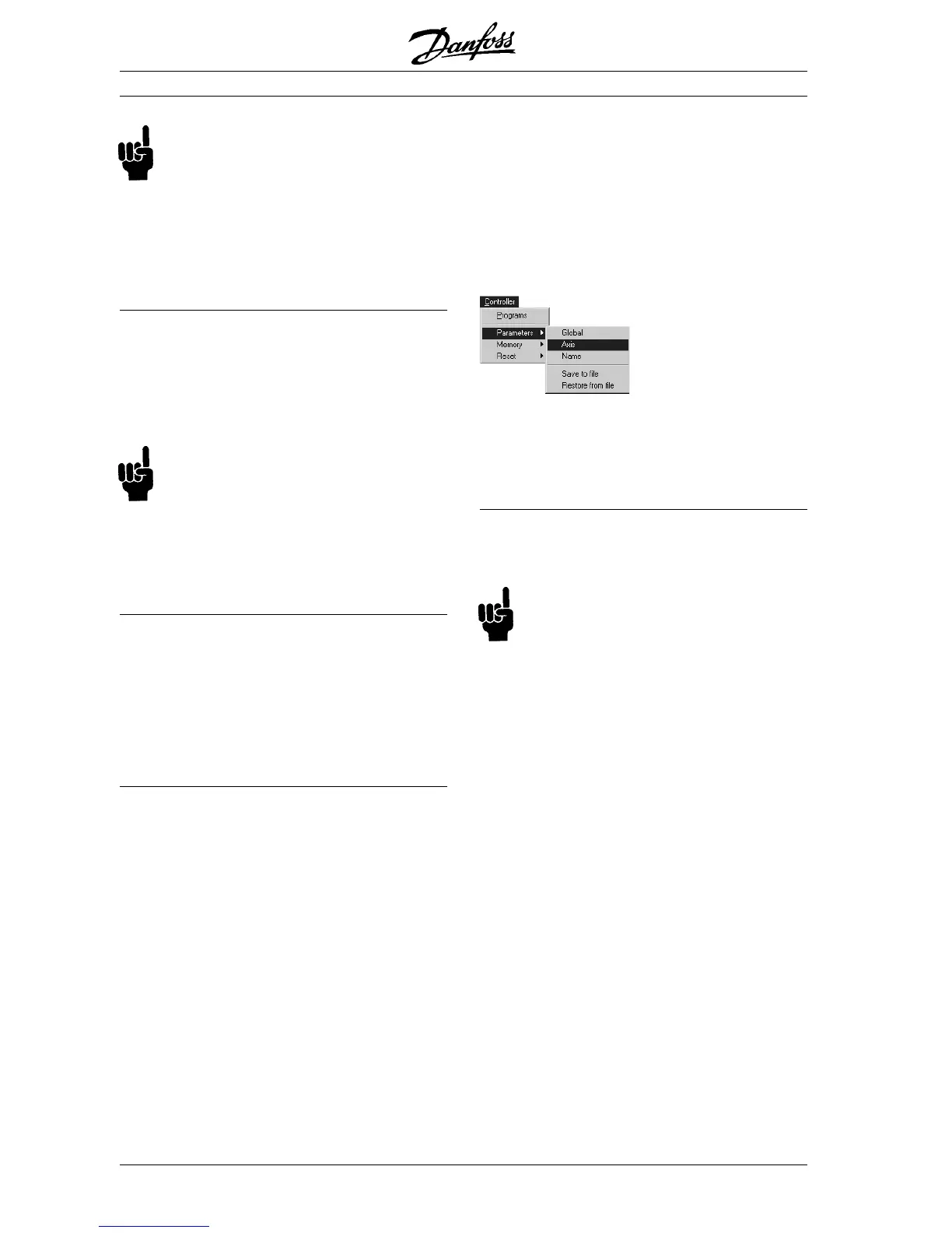
Click on "CONTROLLER" → "PARAMETER" →
"AXIS" and select the VLT, of which you are
currently adjusting the settings.
Setting controller behavior
Before you adjust the controller parameters it is
important to determine which controller behavior
should be achieved.
NB!
The drive elements must never be operated
outside of the technical specifications. Thus
the maximum acceleration is determined by the
“weakest” drive element.
· “Stiff” axis: the fastest reaction possible is
mainly influenced by the
Proportional factorProportional factor
Proportional factorProportional factor
Proportional factor.
You can judge the results on the basis of the
velocity graph.
· Damping of vibrations are mainly influenced
by the
Derivative factorDerivative factor
Derivative factorDerivative factor
Derivative factor. The results can best
be assessed in the velocity graph.
· Temporary (static) deviations in position are
mainly reduced by the
Integral factorIntegral factor
Integral factorIntegral factor
Integral factor and
can best be judged on the basis of the posi-
tioning graph.
Optimizing the PID controller
 Loading...