4.3 Electrical Installation - additional
4.3.1 Electrical Installation, Control Cables
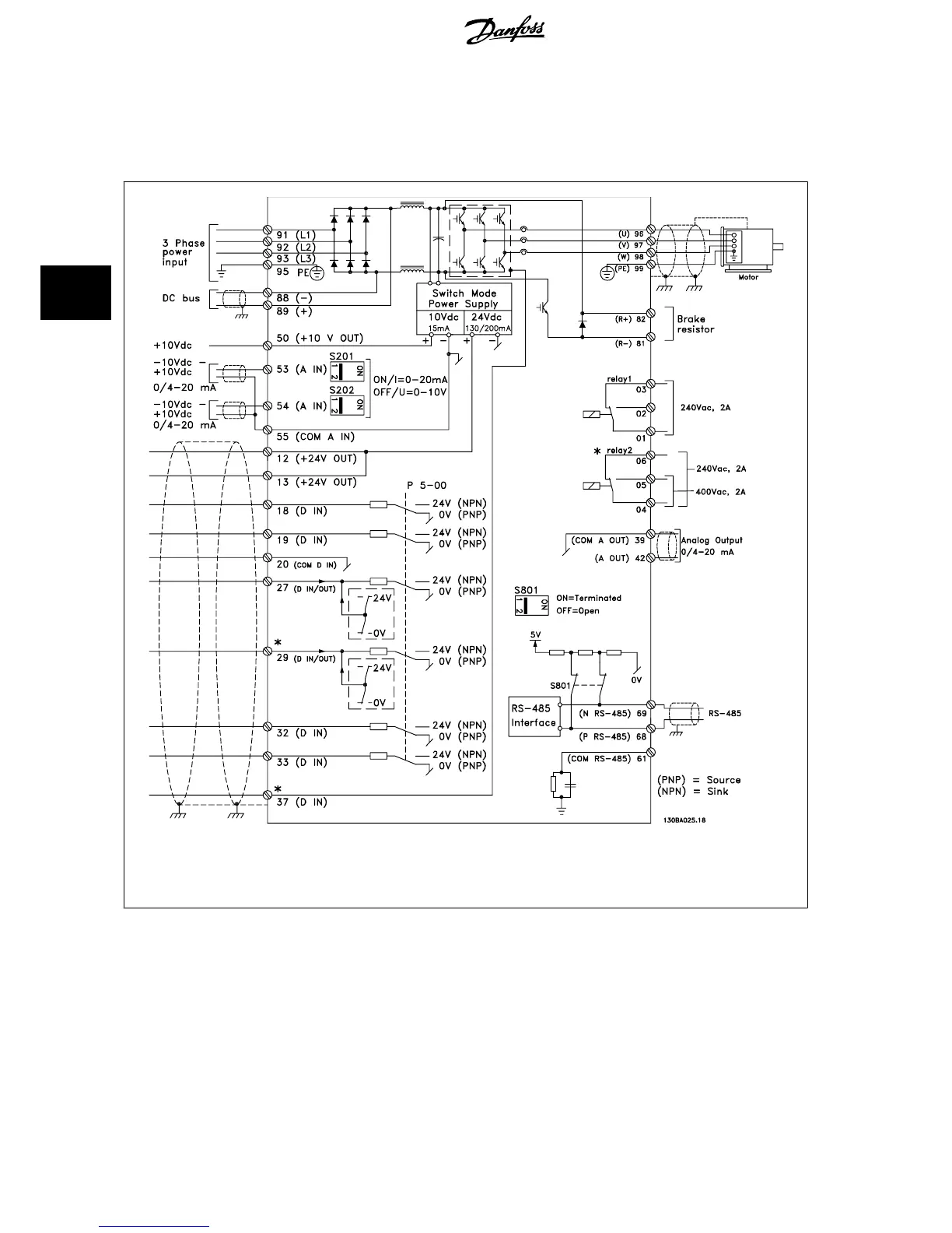
Illustration 4.10: Diagram showing all electrical terminals without options.
Terminal 37 is the input to be used for Safe Stop. For instructions on Safe Stop installation please refer to the section
Safe Stop Installa-
tion
in the frequency converter Design Guide. See also sections Safe Stop and Safe Stop Installation.
Very long control cables and analogue signals may in rare cases and depending on installation result in 50/60 Hz earth loops due to noise from mains
supply cables.
If this occurs, it may be necessary to break the screen or insert a 100 nF capacitor between screen and chassis.
The digital and analog inputs and outputs must be connected separately to the frequency converter common inputs (terminal 20, 55, 39) to avoid earth
currents from both groups to affect other groups. For example, switching on the digital input may disturb the analog input signal.
4 Electrical Installation ADAP-KOOL
®
Drive AKD 102 High Power
48
MG.11.O1.02 - ADAP-KOOL
®
is a registered Danfoss trademark
4
 Loading...