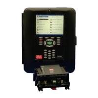
AK-CH 650 Capacity controller RS8ER302 © Danfoss 2016-02 33
4
7
6
5
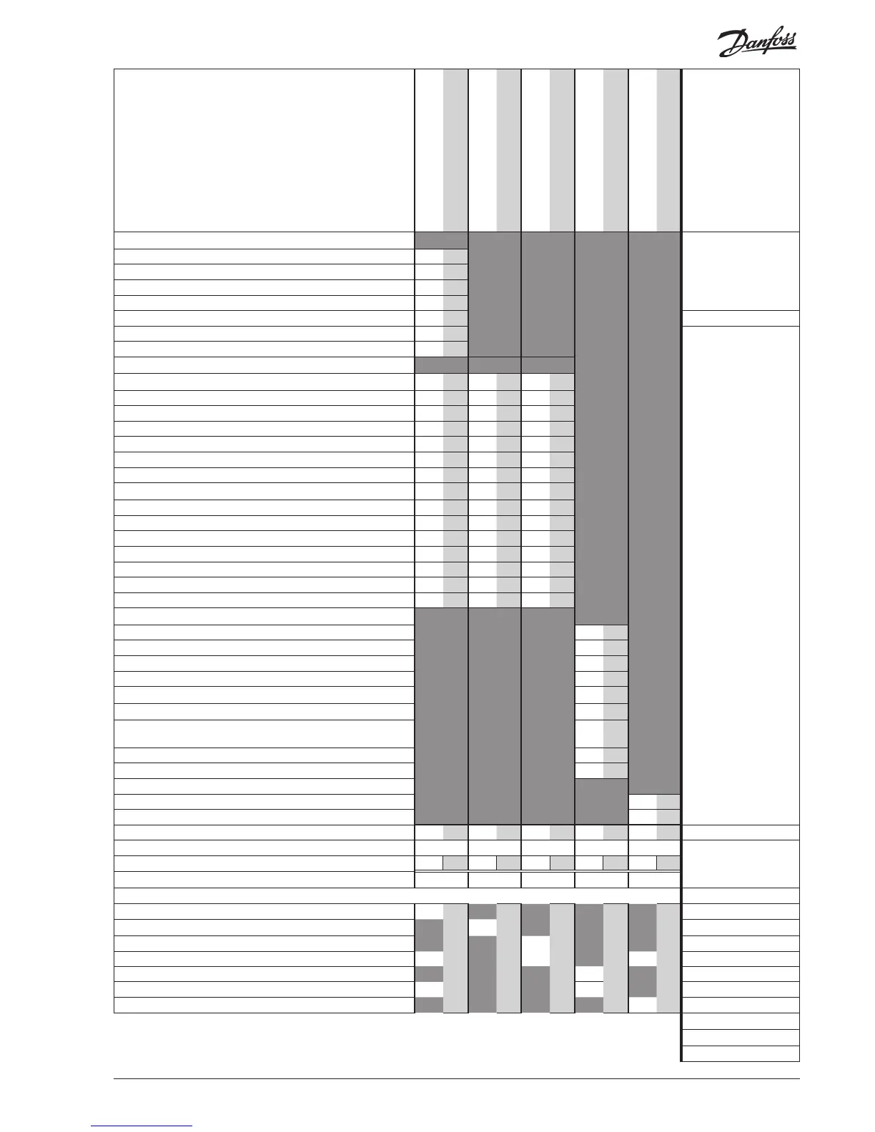
Planning table
The table helps you establish whether there are enough
inputs and outputs on the basic controller.
If there are not enough of them, the controller must be
extended by one or more of the mentioned extension
modules.
Note down the connections you will require and add
them up
Analog input signal
Example
On/o voltage signal
Example
On/o voltage signal
Example
On/O output signal
Example
Analog output signal 0-10 V
Example
Limitations
Analog inputs
Temperature sensors, S3, S4, S7 2
Temperature sensors, Ss, Sd 2
Outdoor temperature sensor, Sc3 1
Extra temperature sensor / separate thermostats
1
Pressure transmitters, P0, Pc, separate pressostats
2 P = Max. 5 / module
0-10 V signal from other regulation, separate signals
Heat recovery via thermostat
On/o inputs
contact 24 V 230 V
Safety circuits, frost protection
1
Safety circuits, Oil pressure
Safety circuits, comp. Motor protection /Motor temp.
Safety circuits, comp. High pres. thermostat
Safety circuits, comp. High pres. pressostat
Safety circuits, general for each compressor
4
Safety circuits, condenser fans
Safety circuits, frequency converter, comp. / cond.
1
Defrost start
External start/stop 1
Night setback of suction pressure
Flow switch
Separate alarm functions
1 1
Heat recovery via DI
Capacity limitations 1
On/o outputs
Compressors (motors) (extra capacity)
4
Unloaders
Fan motors
4
Alarm relay
1
Pumps
2
Defrost output
1
Separate thermostat and pressostat functions and voltage
measurements
1
Heat recovery function
Liquid injection in suction line and heat exchanger 1
Analog control signal, 0-10 V
Frequency converter compressor / condenser 1
Signal cutin compressor capacity
Sum of connections for the regulation
11 0 7 14 1 Sum = max. 80
Number of connections on a controller module
11 11 0 0 0 0 8 8 0 0
Missing connections, if applicable
- - 7 6 1
The missing connections to be supplied by one or more extension modules:
Sum of power
AK-XM 101A (8 analog inputs)
___ pcs. á 2 VA = __
AK-XM 102A (8 digital low voltage inputs)
___ pcs. á 2 VA = __
AK-XM 102B (8 digital high voltage outputs)
1
___ pcs. á 2 VA = __
AK-XM 103A (4 analog inputs 4 analog outputs) ___ pcs. á 2 VA = __
AK-XM 204A / B (8 relay outputs)
1
___ pcs. á 5 VA = __
AK-XM 205A / B (8 analog inputs + 8 relay outp.)
___ pcs. á 5 VA = __
AK_OB 110 (2 analog outputs)
1
___ pcs. á 0 VA = 0
1 pcs. á 8 VA = 8
Sum =
Sum = max. 32 VA
The example:
None of the 3 limitations are exceeded => OK

 Loading...