62 Capacity controller RS8ER302 © Danfoss 2016-02 AK-CH 650
Conguration of inputs
and outputs
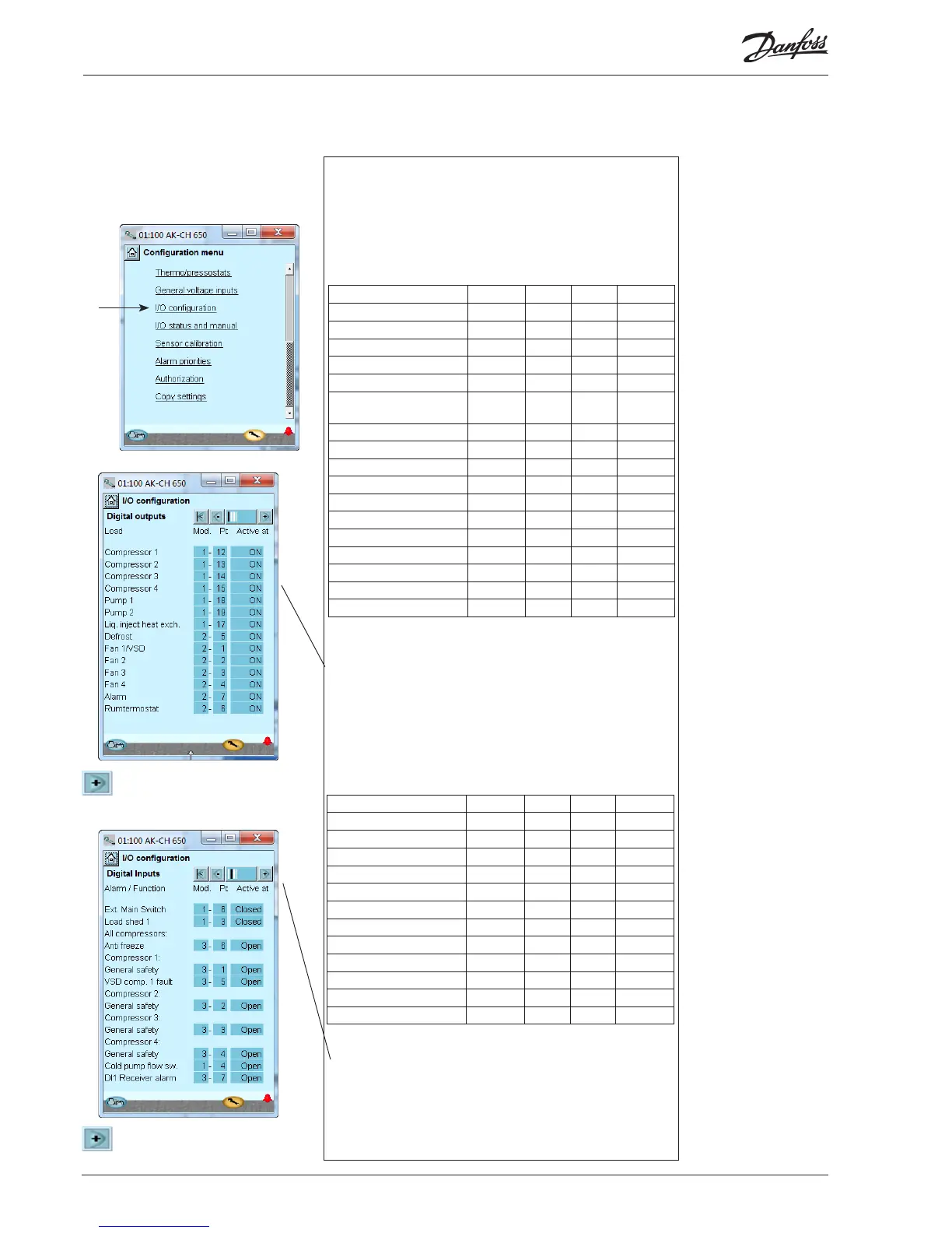
1. Go to Conguration menu
2. Select I/O conguration
3. Conguration of Digital outputs
Press the +-button to go on to the
next page
4. Setup On/o input functions
Press the +-button to go on to the
next page
Conguration - continued
The following displays will depend on the earlier denitions. The
displays will show which connections the earlier settings will require.
The tables are the same as shown earlier.
• Digital outputs
• Digital inputs
• Analog outputs
• Analog inputs
We set up the controller’s digital input functions by keying in which
module and point on this module each one of these has been connected
to.
We furthermore select for each output whether the function is to be ac-
tive when the output is in pos. Closed or Open.
Open has been selected here for all the safety circuits. This means that
the controller will receive signal under normal operation and register it
as a fault if the signal is interrupted.
Load Output Module Point Active at
Compressor 1 / VSD DO1 1 12 ON
Compressor 2 DO2 1 13 ON
Compressor 3 DO3 1 14 ON
Compressor 4 DO4 1 15 ON
DO5 1 16
Liq.injec. in heat ex-
changer
DO6 1 17 ON
Pump 1 DO7 1 18 ON
Pump 2 DO8 1 19 ON
Fan 1 DO1 2 1 ON
Fan 2 DO2 2 2 ON
Fan 3 DO3 2 3 ON
Fan 4 DO4 2 4 ON
Defrost DO5 2 5 ON
Fan in plant room DO6 2 6 ON
Alarm DO7 2 7 OFF !!!
DO8 2 8
!!! The alarm is inverted so that there will be an alarm if the supply
voltage to the controller fails.
We set up the controller’s digital outputs by keying in which module
and point on this module each one of these has been connected to.
We furthermore select for each output whether the load is to be active
when the output is in pos. ON or OFF.
3 - Outputs
The possible functions are
the following:
Comp. 1
Unloader 1-1, 1-2, 1-3
Comp. 2-6
Extra cooling
Cold pump 1
Cold pump 2
Injec. in suction line
Injec in heat exchanger
Defrost
Fan 1 / VSD
Fan 2 - 8
Hest recovery
Alarm
Thermostat 1 - 5
Pressostat 1 - 5
Voltage input 1 - 5
4 - Digital inputs
The possible functions are
the following:
Ext. Main switch
Night setback
Load shed 1
Load shed 2
Frost protection
All compressors:
Compressor. __
Oil pressure safety
Over current safety
Motor protect. safety
Disch. temp. safety
Disch. press. safety
General safety
VSD comp_. error 1-2
Flow switch (cold pump)
Cold pump 1 monitoring
Cold pump 2 monitoring
Fan 1 protection
Fan 2......8 protection
VSD Cond. protection
Heat recovery
DI Alarm 1
DI Alarm 2.....10
Defrost
Function Input Module Point Active at
Consumpt. limit AI3 1 3 Closed
Pump ow switch AI4 1 4 Open
External main switch AI6 1 6 Closed
Compressor 1 Gen. Safety DI1 3 1 Open
Compressor 2 Gen. Safety DI2 3 2 Open
Compressor 3 Gen. Safety DI3 3 3 Open
Compressor 4 Gen. Safety DI4 3 4 Open
VSD, comp. speed DI5 3 5 Open
Frost protection DI6 3 6 Open
Receiver level on/o DI7 3 7 Open

 Loading...