AK-CH 650 Capacity controller RS8ER302 © Danfoss 2016-02 55
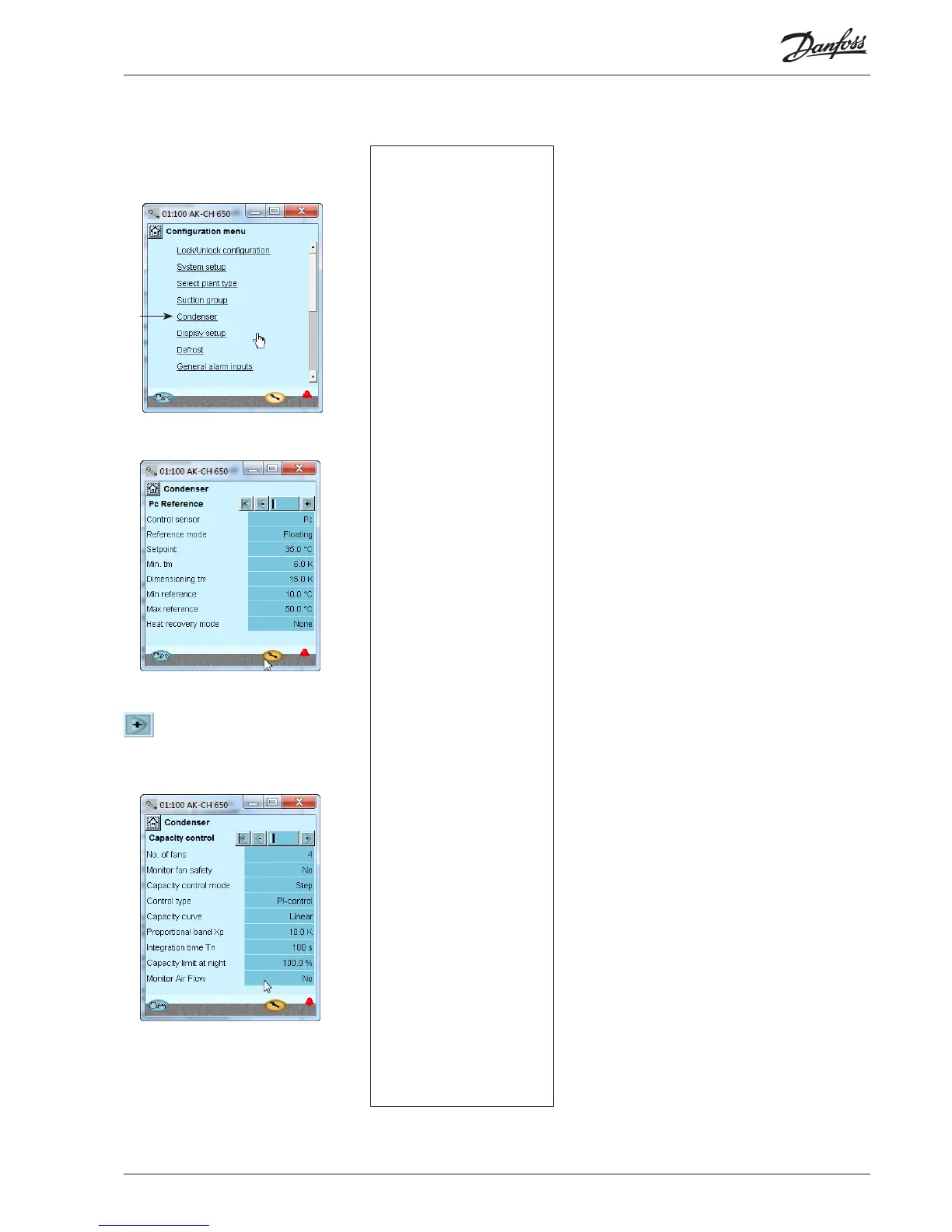
1. Go to Conguration menu
2. Select Condenser
3. Set control mode and reference
Press the +-button to go on to the
next page
4. Set values for capacity regulation
Conguration - continued
For your information the function
”Monitor fan safety” will require an
input signal from each fan.
In our example the condenser
pressure is controlled on the
basis of the outdoor temperature
(oating reference).
The settings shown here in the
display.
Used in our example are four step-
controlled fans.
The settings shown here in the
display.
3 - PC reference
Control sensor
Pc: The condensing pressure PC is used for regulation
S7: Media temperature is used for regulation
Reference Mode
Choice of condenser pressure reference
Fixed setting: Used if a permanent reference is required =
“Setting”
Floating: Used if the reference is changed as a function of Sc3
the external temperature signal, the congured "Dimension-
ing tm K"/"Minimum tm K" and the actual cut in compressor
capacity.
Setpoint
Setting of desired condensing pressure in °C
Min. tm
Minimum average temperature dierence between Sc3 air
and Pc condensing temperature with no load.
Dimensioning tm
Dimensioning average temperature dierential between Sc3
air and Pc condensing temperature at maximum load (tm
dierence at max load, typically 8-15 K).
Min reference
Min. permitted condenser pressure reference
Max reference
Max. permitted condenser pressure reference
Heat recovery mode
Choice of method for heat recovery
No: Heat recovery not used
Thermostat: Heat recovery operated from thermostat
Digital input: Heat recovery operated from signal on a digital
input.
Heat recovery relay
Choose whether an output is required that should be acti-
vated during heat recovery.
Heat recovery ref
Reference for the condensing pressure, when heat recovery
is activated.
Heat recovery ramp down
Congure how quickly the reference for the condenser
pressure should be ramped down to normal level after heat
recovery. Congure in Kelvin per minute.
Heat recovery cutout
Temperature value where the thermostat cuts-out the heat
recovery.
Heat recovery cutin
Temperature value where the thermostat cuts-out the heat
recovery.
4 - Capacity control
Pc Refrigerant
Select refrigerant
Pc refrigerant factors K1, K2, K3
Only used if “Pc refrigerant type” is set to custom (contact
Danfoss for information)
No of fans
Set number of fans.
Monitoring fan safety
Safety monitoring of fans. A digital input is used to monitor
each fan.
Capacity control mode
Select control mode for condenser
Step: Fans are step-connected via relay outputs
Step/speed: The fan capacity is controlled via a combination
of speed control and step coupling
Speed: The fan capacity is controlled via speed control (fre-
quency converter)
Speed control on rst step, rest=step
Control type
Choice of control strategy
P-band: The fan capacity is regulated via P-band control. The
P band is congured as "Proportional band Xp"
PI-Control: The fan capacity is regulated by the PI controller.
Capacity curve
Choice of capacity curve type
Linear: The same amplication in the entire area
Square: Square curve shape, which gives higher amplication
at higher loads.
Setup control of condenser

 Loading...