Installation
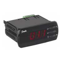
The controller must be connected to the RS-485 adapter via an interface cable (080N0327). Remember to fasten the
cable plug to the controller via the cable clip, see Figure 14. Please refer to the installation guide for RS-485 adapter
(EKA 206) for detailed instruction on how to install the adapter correctly.
Figure 14: Correct mounting of cable
and cable clip
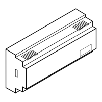
The other end of the cable must be plugged into the RS-485 adapter.
Figure 15: Connection of RS-485
adapter
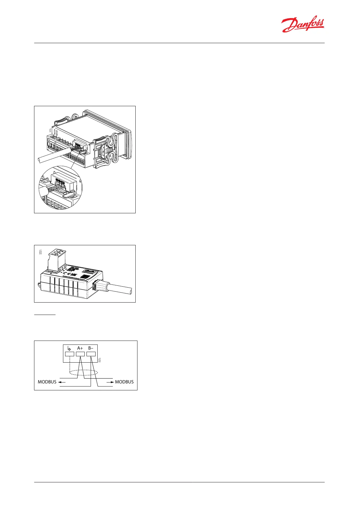
Wiring
The Modbus cable must be wired as shown in Figure 16.
Figure 16: Modbus cable
Danfoss
80G8440
B–
MODBUS MODBUS
A+
Operation
When the controller is powered up, the two LEDs placed next to the terminal block on the RS-485 adapter will show
the data communication taking place. The Tx LED (green) indicates when the controller transmits a message on
Modbus and the Rx LED (yellow) indicates data communication on the Modbus.
Case controller, type EKC 223 and EKC 224
© Danfoss | Climate Solutions | 2023.05 BC432222569027en-000201 | 16
 Loading...