1.
2.
5 User Interface
In this section the user interfaces are described. EKE 1x controllers can be used with 2 main user interfaces:
• MMI display
• KoolProg Software
5.1 Conguration using MMI Display
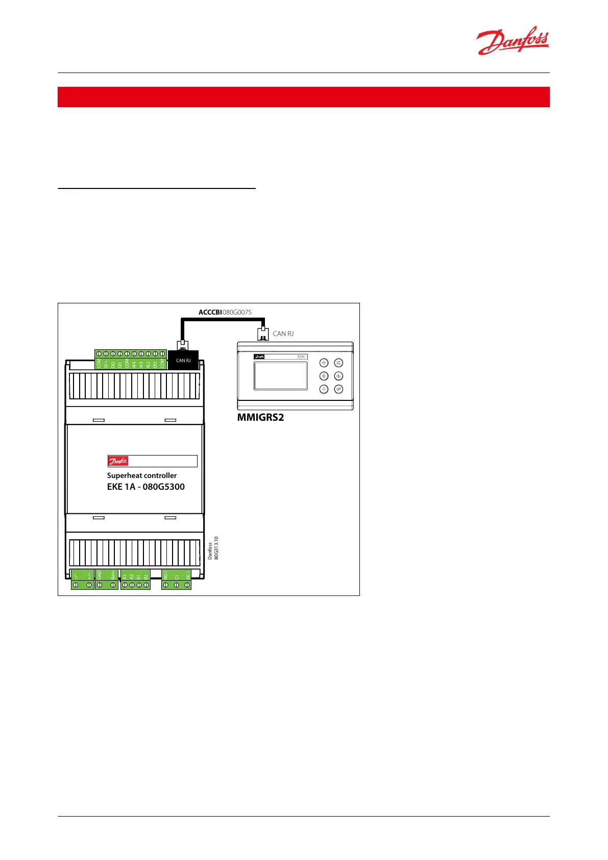
MMIGRS2 is a graphical display. The connection with each EKE controller is made through the CAN RJ or CANBus
network. All the information about the user interface is loaded inside the EKE controller. that’s why there is no need
of programming the MMIGRS2 interface.
MMIGRS2 is powered externally or from the controller (while using RJ12) which it is connected to and automatically
shows its user interface. EKE can be congured with basic settings quickly using the wizard setup and advanced
settings can be made afterwards.
Figure 30: Connecting MMIGRS interface
–/~
+/~
GND
Bat+
A1
A2
B1
B2
NO1
C1
NC1
COM
5V+
DI2
DI1
COM
AI4
AI3
AI2
DI3
COM
CAN RJ
Danfoss
80G313.10
MMIGRS2
ACCCBI080G0075
CAN RJ
–/~
+/~
GND
Bat+
A1
A2
B1
B2
NO1
C1
NC1
COM
5V+
DI2
DI1
COM
AI4
AI3
AI2
DI3
COM
CAN RJ
Superheat controller
EKE 1A - 080G5300
When MMI is not connected to EKE via CANRJ12 the autodetection feature of the EKE CAN address will not work.
Therefore, check the following MMIGRS2 setting:
enter BIOS menu pressing and holding X + Enter keys for 5 s.
select “MCXselection”->” Manual Mode” and set the CAN address of the EKE you wish to connect to. CAN H-CAN
R shorting should be done only on the rst and last node of the network.
For the series EKE 1C and EKE 1D, to connect via MMI via the wired CAN, the R and H terminal of the MMI needs to
be shorted.
Superheat controller, Type EKE 1A, 1B, 1C, 1D
© Danfoss | Climate Solutions | 2022.06 BC398828796060en-000101 | 26
 Loading...


