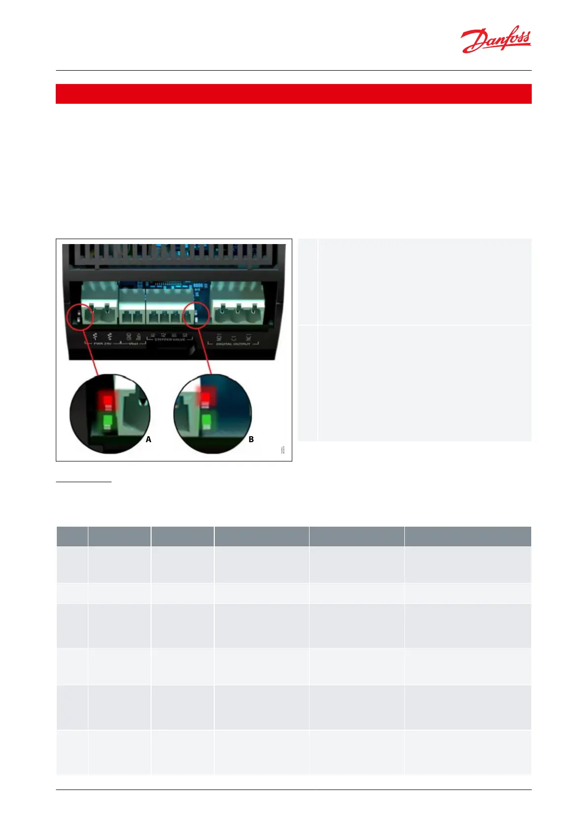
Two status LEDs to indicate operational status
• Steady green = power ON
• Flashing green = data transmission /
initialization
• Flickering red = alarm / error condition
Two status LEDs to indicate valve operation
• Flashing red = valve closing
• Steady red = valve fully closed
• Flashing green = valve opening
• Steady green = valve fully open
• Both green and red ashing = valve-related
alarm
8 Alarms and troubleshooting
Depending on the application, the EKE 1x series implements error codes and alarms to help the user troubleshoot
and correct parameters easily. When an alarm occurs, the following actions generally ensue:
• the “Alarm” or “Warning” relay is activated
• an icon and the alarm code are displayed on the screen
The alarms are reset automatically. The alarm is deactivated as soon as the alarm condition ceases. Otherwise, the
user must follow the deactivation procedure once the alarm conditions is over. When the alarm is eliminated the
alarm, relay is deactivated, and the alarm code will no longer be displayed.
Figure 85: LED indication
8.1 Alarms
8.1.1 Conguration errors
Table 55: Conguration errors
Trigger (how the alarm IS
raised)
Active when: - D12 and D13
have the same mapping cong-
uration. - All and AI5 have the
same mapping conguration.
Correct application settings
One or more
conguration errors is block-
ing operation to start. Check the other ac-
tive alarms to identify the conguration
problem.
0030 refrigerant set to none
Set 0030 refrigerant set to an
actual refrigerant
No refrigerant is selected,
congure the
correct refrigerant. See "0030 Refrigerant"
SH reference too
close to SH close set
point
SH close is used and SH close
set pint is too close the actual
reference/ reference minimum
Disable SH close or correct the
actual SH reference / reference
minimum to have 0.5K dier-
ence to SH close set point
SH reference can come to close to the SH
close safety functions et point. which can
result in unstable operation. Keep min.
0.5K separation between minimum SH ref-
erence and N119 SH close set point.
LOP set point too
close to MOP set
point
If MOP and LOP is used, Mop
set point - Lop set point must >
5K
Disable MOP or LOP, or adjust
the dierence on MOP-LOP set
point >= 5K
The set point for the 2-pressure safety
function Lop and Mop is to close. Keep
min. 5K separation between NO11 MOP
set point and N140 LOP set point
No sensor
cong-
ured for S4
Application need a S4 signal for
either thermostat or Min S4.
but S4 signal is congured
Disable the functions needing
S4 or congure a S4 signal
Operation is
congured to use S4 (media
out) sensor, but no S4 sensor is congured.
Correct I020 All conguration or AI5 con-
guration and check I042 S4 sensor cong-
uration
No sensor
cong-
ured for S3
Thermostat need a S3 signal
and no s3 signal is congured
Disable the functions needing
S4 or congure a S4 signal
Operation is
congured to use S3 (media
in) sensor, but no S3 sensor is congured,
Correct 1020 All conguration or AI5 con-
guration and check I041 S3 sensor cong-
uration
Superheat controller, Type EKE 1A, 1B, 1C, 1D
© Danfoss | Climate Solutions | 2022.06 BC398828796060en-000101 | 72
 Loading...


