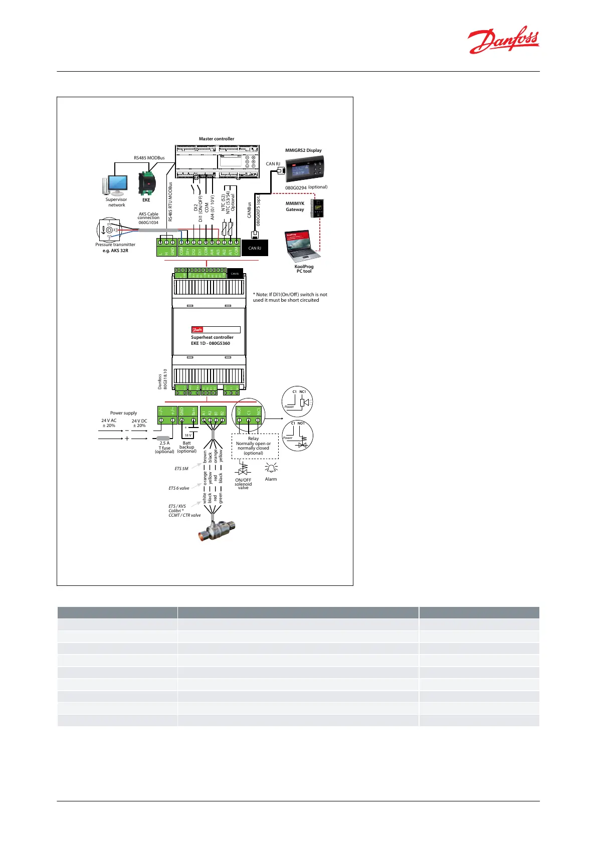
Figure 4: EKE 1B connection overview
Danfoss
80G318.10
COM
5V+
DI2
DI1
COM
AI4
AI3
AI2
DI3
COM
L
H
GND
CAN RJ
–/~
+/~
GND
Bat+
A1
A2
B1
B2
NO1
C1
NC1
COM
5V+
DI2
DI1
COM
AI4
AI3
AI2
AI1
COM
CAN RJ
–/~
+/~
GND
Bat+
A1
A2
B1
B2
NO1
C1
NC1
–
+
+
18 V
1
2
3
COM
5V+
DI2
DI1
COM
AI4
AI3
AI2
DI3
COM
L
H
GND
CAN RJ
–/~
+/~
GND
Bat+
A1
A2
B1
B2
NO1
C1
NC1
COM
5V+
DI2
DI1
COM
AI4
AI3
AI2
AI1
COM
CAN RJ
–/~
+/~
GND
Bat+
A1
A2
B1
B2
NO1
C1
NC1
C1
NC1
Power
C1
NO1
Power
Superheat controller
EKE 1D - 080G5360
Master controller
Pressure transmitter
e.g. AKS 32R
Power supply
24 V AC
± 20%
24 V DC
± 20%
2.5 A
T fuse
(optional)
Batt
backup
(optional)
ON/OFF
solenoid
valve
Alarm
Relay
Normally open or
normally closed
(optional)
AKS Cable
connection
060G1034
* Note: If Dl1(On/Off) switch is not
used it must be short circuited
RS485 MODBus
RS485 RTU MODBus
Supervisor
network
EKE
MMIGRS2 Display
MMIMYK
Gateway
KoolProg
PC tool
080G0294
(optional)
CANBus
0
80G0075 (opt.)
DI2
DI1 (ON/OFF)*
COM
AI4 (0 / 10 V)
NTC (S2)
NTC (S3/S4)
Optional
CAN RJ
orange
yellow
red
black
brown
black
orange
yellow
white
black
red
green
ETS 6 valve
ETS 5M
ETS / KVS
Colibri ®
CCMT / CTR valve
Table 7: EKE 1B pinout
S3/S4 selectable via software
Analog inputs 0 – 5 V / Ratiometric pressure transmitter
External Reference signal
Power output for Ratiometric pressure transmitter 0 – 5V
NOTE:
• If Dl1(On/O) switch is not used it must be short circuited
• EKE 2U Backup power module is recommended to use to ensure closure of the electronic valves. in case of power
failures
© Danfoss | Climate Solutions | 2022.06 BC398828796060en-000101 | 9
Superheat controller, Type EKE 1A, 1B, 1C, 1D
 Loading...


