The response from the slave to the master will be:
Example - Reading a parameter value:
The value in parameter 207 Ramp up time 1 is re-
quired.
The master sends the following request:
PKE = 10CF Hex - read parameter 207 Ramp
up time 1
IND = 0000 Hex
PWE
HIGH
= 0000 Hex
PWE
LOW
= 0000 Hex
If the val-
ue in parameter 207 Ramp-up time 1 is 10 sec., the
response from the slave to the master will be:
Conversion:
Under the section entitled Factory Settings the various
attributes of each parameter are displayed. As a pa-
rameter value can only be transferred as a whole
number, a conversion factor must be used to transfer
decimals.
Example:
Parameter 201 Output frequency, low limit f
MIN
has a
conversion factor of 0.1. If you wish to preset the min-
imum frequency to 10 Hz, the value 100 must be
transferred, as a conversion factor of 0.1 means that
the value transferred is multiplied by 0.1. The value
100 will thus be perceived as 10.0.
Conversion table
Conversion
index
Conversion
factor
74 0.1
2 100
1 10
0 1
-1 0.1
-2 0.01
-3 0.001
-4 0.0001
-5 0.00001
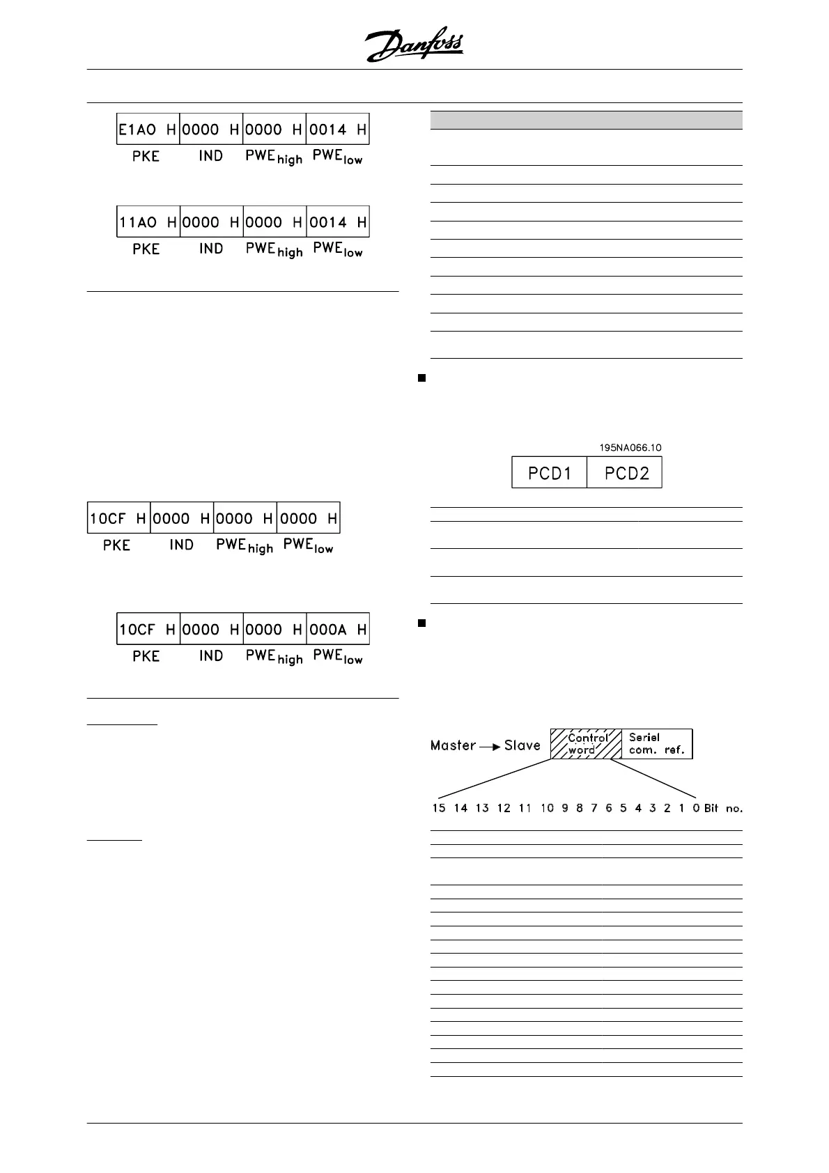
Process Words
The block of process words is divided into two blocks
of 16 bits, which always occur in the defined sequence.
PCD 1 PCD 2
Control telegram
(master ⇒ slave)
Control word Reference-
value
Control telegram
(slave ⇒ master)
Status word Present outp.
frequency
Control Word According to FC Profile
To select FC protocol in the control word, parameter
512 Telegram Profile must be set to FC protocol [1].
The control word is used to send commands from a
master (e.g. a PC) to a slave (frequency converter).
Bit Bit = 0 Bit =1
00 Preset reference choise lsb
01 Preset reference choise
msb
02 DC brake Ramp
03 Coasting Enable
04 Quick stop Ramp
05 Freeze output Ramp enable
06 Ramp stop Start
07 No function Reset
08 No function Jog
09 Ramp 1 Ramp 2
10 Data not valid Valid
11 No function Relay 01 activated
12 No function Relay 04 activated
13 Choice of Setup (lsb)
14 Choice of Setup (msb)
15 No function Reversing
VLT
®
5000 Design Guide
88 MG.52.B2.02 - VLT
®
is a registered Danfoss trademark
 Loading...


